 |
|

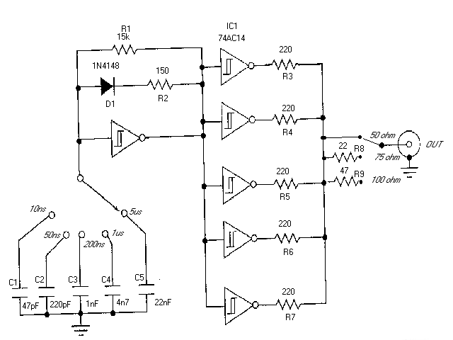
Component list:
R1       15 kohm
R2       150 ohms
R3-R7    220 ohms
R8       22 ohms
R9       47 ohms
C1       47 pF
C2       220 pF
C3       1 nF
C4       4.7 nF
C5       22 nF
D1       1N4148
IC1      74AC14
NOTE: Do not try to substitute IC1 with any other type of IC because the circuit does not work correctly if other 7414 IC type than 74AC14 is used (74HC14 and 74HCT14 do not work well).
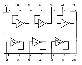
below you can see the pinout if the 74AC14 IC. It is the main IC if the circuit.

It should not matter which of the ports you use for different parts of the circuit. My recommendation is to use port connected to pins 1 and 2 for the function of the leftmost gate in circuit diagram (the oscillator). Use the rest of the gates for the burering stage (five gates in parallel on the right).
This circuit is best powered with 4.5V battery or three 1.5V batteries connected in series. The + from battery goes to IC1 pin 14. The pin 7 of IC1 is connected to circuit ground which is connected to circut ground. Remeber to put a 100 nF (ceramic or polypropylene) capacitor between IC1 pins 7 and 14 to guarantee stable operating voltage for the circuit.
TDRs are used in all phases of a cabling system's life, from construction to maintenance and to fault finding. Historically, the TDR has been reserved for only large companies and high level engineers. This was due to the complexity of operation and high cost of the instruments.
If a cable is metal and it has at least two conductors, it can be tested by a TDR. TDRs will troubleshoot and measure all types of twisted pair and coaxial cables. TDRs can locate major or minor cabling problems including; sheath faults, broken conductors, water damage, loose connectors, crimps, cuts, smashed cables, shorted conductors, system components, and a variety of other fault conditions. TDR can be used to locate the problem type and in which place along the calbe the fault is.
The TDR works on the same principle as radar. When that pulse reaches the end of the cable, or a fault along the cable, part or all of the pulse energy is reflected back to the instrument. Any impedance change in cable will cause some energy to reflect back toward the TDR and will be displayed. How much the impedance changes determines the amplitude of the reflection. The TDR measures the time it takes for the signal to travel down the cable, see the problem, and reflect back. The TDR then displays the reflected signal as information on waveform display.
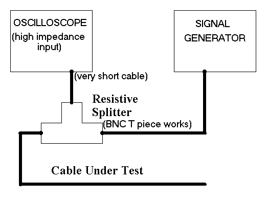
This circuit in this article is made to be used with a normal oscilloscope. The circuit which you build is used as the signal source and the oscilloscope is used as a waveform monitor. Connection diagram:

Possible resistive splitter configurations:
                      to oscilloscope
                           |
                           |
                           |
  cable under test --------+--------- signal generator
                      to oscilloscope
                           |
                          | |
                          | | 1 kohm
                          |_|
                           |
  cable under test --------+--------- signal generator
                      to oscilloscope
                           |
                          | |
                          | | 17 ohm
                          |_|
                     ___   |   ___
  cable under test -|___|--+--|___|-- signal generator
                    17 ohm    17 ohm
Many TDRs have selectable pulse width settings. The larger the pulse width, the more energy is transmitted and therefore the further the signal will travel down the cable.
The pulse that the TDR generates takes a certain amount of time to lauch, and at this time the start of pulse has already travelled through the cable some distance. This distance is known as the blind spot. The size of the blind spot varies with the pulse width. The larger the pulse width, the larger the blind spot. It is difficult to locate a fault contained within the blind spot.
Short pulses are ment to test short cables and to locate faults nearby. If the fault is very small or cable is very long, the signal strength of a a very short pulse may not be enough to travel down the cable, "see" the fault, and travel back. In this case you need to use longer pulse. Sometimes, larger pulse widths are helpful even for locating faults that are relatively close. If the fault (impedance mismatch) is very small, the signal strength of a small pulse may not be enough to travel down the cable, .see. the fault, and travel back. The attenuation of the cable combined with the small reflection of a partial fault can make it difficult to detect. A larger pulse width transmits more energy down the cable, making it easier for the TDR to detect a small fault.
This circuit includes settings from 10 nanoseconds to 5 microseconds. The blind spot for 10 nanosecond pulse is around 4 meters. With 1 microseconed pulse the blind spot is around 100-130 meters depending on cable speed.
When you look at the oscilloscope screen you first see the transmitted pulse and sometime after it you will see the reflected pulse. The second pulse has the following characteristics on different fault conditions:
TDRs are extremely accurate instruments. Baslicly the accuracy depends on how accurately you can "read" the pulses on your oscilloscope screen (hoe well they can be "read" and how accurate your oscilloscope timing is). The accuracy does not depends on how accurate components you have used on your pusle signal source. However, variables in the cable itself can cause errors in distance measurements. When locting distance, you shoul always know correct Velocity of Propagation (VOP) of the cable being tested.
Make a quality connection between the instrument and the cable under test. The importance of a quality connection cannot be overstated. It is best if the cable is adapted to connect directly to the front panel of the instrument. Use adapters, connectors and jumper cables with the same impedance as the cable under test. A poor connection can result in a distorted waveform that can mask a fault. Remeber to select also right impedance setting from the signal source (the one that matches bet the cable you use).
It is possible to use a TDR to find an approximate value of cable attenuation. Compare the amplitudes of the sent pulse and reflected pulse. Since the TDR has both the signal source and the receiver located at the same end, the signal will have twice the attenuation because the signal has traveled down and back along the cable. Therefore, if you simply divide the dBRL value by 2, you will have the approximate value of the cable attenuation at that frequency and cable length. Remember, each pulse width has a specific fundamental frequency and cable attenuation is frequency sensitive. Note the cable length, the pulse width setting, and the return loss of the connections. Make sure the far end of the cable under test is not connected to a terminator or any other piece of equipment.
Structural return loss can be viewed on a TDR by looking at the base line of the waveform. A perfectly flat baseline indicates a high quality cable with no damage or structural return loss. A bumpy baseline would indicate a low-quality cable, damage, and/or structural return loss.
Note: Sometimes DC or low frequency distortion occurs when a pulse is transmitted on a highly capacitive cable such as telephone twisted pair.
Experiment with the TDR on known cable lengths and conditions. Learn to identify waveform signatures and the function of each key. Become familiar with the instrument prior to actual field applications. A variety of waveforms may be encountered during testing. This variety is due to the different applications, electrical, and environmental characteristic variations found in the cables that exist today. A complete understanding of the TDR operation and experience in using the instrument is vital to successful use of TDR. Practice testing on multiple types of known cable segments, with and without components. Become familiar with how each segment looks prior to any problems.
Information on different pulse lengt properties
Pulse length   Fundamental frequency  Blind spot  Approx range (twisted pair)

10 ns            50 MHz                4 m        500 m
50 ns            10 MHz                8 m
200 ns           2.5 MHz               30 m       1.5 km
1 us             500 kHz               100 m      5 km
5 us             100 kHz               600 m
Most information on this tabe are based on technical data given at http://www.riserbond.com/assets/downloads/Appguide.pdf.
Good sites to look for further information how to use a TDR:
|