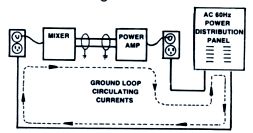
Allen Avionics Audio Isolation Transformers page describes the typical ground loop problem situation with the following drawing:
If you want to do the ground loop elimination in audio path, you have to cut the galvanic connection but pass the whole audio range. The simplest and most common way to do the isolation is use audio transformer. High-quality audio transformers cover whole audio band with good response.
Usually when you install an audio galvanic isolation to almost any place in the audio cable connection is solves the ground loop caused humming problem nicely.
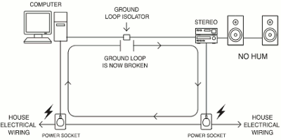
Xitel Ground Loop Isolator page gives a good example how to use a ground loop isolator (audio isolation transformer) to solve ground a typical ground loop problem:
To make an audio isolator you have to get two audio transformers which have 1:1 transformation ratio and greater than 1 kohm impedance (prefererably many kilo-ohms for consumer line level applications). There are high quality audio transformers in the markes that meet those specs.
There are several ways how to wire an audio isolation transformer. Here is a basic wirings for isolation transformers for unbalanced and balanced lines:
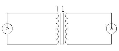
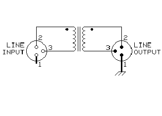
There are variations how ground are wired on different audio isolation transformers. There are various ways with their advantages and disadvantages. The followinf solution circuit diagram from Allen Avionics Audio Isolation Transformers page conbines all different variations to one device, so you can always easily select (with a switch) the one that works best on you specific application:
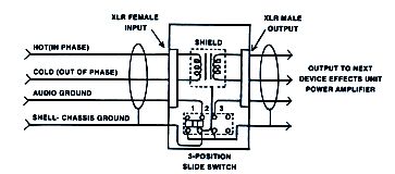
The 3-position switch will eliminate the need to cut pin “1″ to lift the audio ground and the connection to the shield. Switch Positions:
1. Chassis shield connected. Audio ground not connected. Acts as a balanced line transformer to break ground loops. Eliminates hum and buzz.
2. Chassis shield and audio ground connected. Corrects balance on audio lines.
3. Chassis shield and audio ground not connected. Breaks ground loops. Provides audio isolation.
When selecting a transformer for your project keep in mind the quality. Cheapest transformers for audio use have some problems on the sound quality, typically distorted bass response and attenuating in high-frequency response. Basically a poor transformer slows down high frequencies more than low frequencies (because of transformer leakage inductance). This allows the low frequencies to pass first, creating what we perceive as a “fat/warm” tone. Inadequate frequency response on the low end (roll off at like 20Hz), causes low frequencies to be “slowed”, allowing the upper frequencies to be heard first, this is perceived as “barky/ brittle”.
When installing audio isolation transformer to an audio system HIFI people usually ask does that transformer affect the sound in some way and if it does something how much effect does it have. The truth is that the effect of adding an audio audio isolation transformer to a system that does not have ground loop problem could be anything from unnoticeable to normal listener to well noticeable. How much the transformer affects depends on the transformer quality and properties of the equipment between which the transformer is connected. So if there is no humming on the system, the transformer usually has some slightly negative effect on sound quality.
In case an audio transformer is installed to a system with ground loop humming, the effect of it will for sure be possible. The annoying ground loop humming will be heard by everybody. When the isolation transformer get rid of that, the would quality is very much improved at that moment (typically the negative effects of the transformer to sound are much smaller than the annoying humming is). It is a good idea to keep an audio isolation transformer on your tool box when you work with audio/video systems, and use it in you get ground loop problems.
74 Comments
Tomi Engdahl says:
Lightning Boy Audio 2020i Amplifier Isolation Transformer
https://www.youtube.com/watch?v=hxbLgQrL7Lc
The 2020i is specifically an audio isolation transformer, unlike the 2020 Instrument transformer. Its a different product is not interchangeable with the 2020 Instrument Transformer. Aside from a different application, it does have the same transformer in it as the Instrument Transformer. The big difference with the 2020i is there is no ground connection between the input and output jacks. Due to this, there is only one practical application for the 2020i and that is to eliminate ground loop noise in multi-amplifier guitar rigs, ie. a stereo rig. Whenever you have more than one path to ground you have a ground loop. The transformer is an LBA-2020, which is wound in-house by Lightning Boy Audio. The 2020i is available direct from Lightning Boy Audio
https://lightningboyaudio.com/isolationtransformer.html
Tomi Engdahl says:
Lightning Boy Audio 2020S Steel-Core Instrument Transformer
https://www.youtube.com/watch?v=tDJ2omHGmLY
Tomi Engdahl says:
How to make the audio transformer
https://www.youtube.com/watch?v=KRNljBm8c2E
Winding the output transformer for vaccum tube audio.
Tomi Engdahl says:
Inside an audio isolator transformer module
https://m.youtube.com/watch?v=fV_hsFK1MnA&fbclid=IwAR1zbBOA3YtDofoJP1gdWs24qxU0iaAl0DxIBPPdNGia8iTkKGilLKldH44
Tomi Engdahl says:
Audio Transformer Measurements and Modeling
https://www.onallbands.com/audio-transformer-measurements-and-modeling/
This page presents measured data for selected audio transformers and shows how well the measurements permit the transformers to be modeled using LTSpice. The transformers selected are ones that might be considered for ground loop isolation when used with Softrock receivers, or when computer-based data transmission/reception programs are used with receivers or transceivers.
Tomi Engdahl says:
Step Up Transformers SUT for Moving Coil Cartridges Explained – SUT Series Part 1
https://www.youtube.com/watch?v=dzqq19OfpHM
BG133 – An explanation of how Step-Up Transformers for Moving Coil Phono Cartridges work.
Building a Step Up Transformer for Moving Coil Cartridges MC – SUT Series Part 3
https://www.youtube.com/watch?v=t7HtaTGP1v0
Tomi Engdahl says:
DIY ground loop isolator audio noise filter or hum eliminator
https://www.youtube.com/watch?v=6Gc8nZG_-F8
Tomi Engdahl says:
1:1 600ohms between a dac and a tube preamp idea
WE111c belongs on the mix bus for a vibe-y country record!
https://gearspace.com/board/geekzone/858721-western-electric-111c-di-box.html
https://educ.jmu.edu/~fawcetwd/archive/repeatcoil.pdf
https://www.hifido.co.jp/sold/01-07700-05513-00.html?LNG=E
WE111C are a wrong and expensive choice for this. Despite much internet folklore they are all but invisible in the audio path, …
https://groupdiy.com/threads/wtb-western-electric-111c-or-similar-audio-transformers.72787/
Tomi Engdahl says:
Yep. 30-15K +_ 0.5dB – sounds like a real plan to increase fidelity. A repeating coil with a ratio of 600/xxx ohm. Who knows what phase shift or other nasties come in addition to the reduction in frequency response. I wonder who builds stereo equipment to this spec?
https://educ.jmu.edu/~fawcetwd/archive/repeatcoil.pdf
This belongs in a museum.
Tomi Engdahl says:
Discussion from https://www.facebook.com/groups/DIYAudio/permalink/5804745299591268/
Yep. 30-15K +_ 0.5dB – sounds like a real plan to increase fidelity. A repeating coil with a ratio of 600/xxx ohm. Who knows what phase shift or other nasties come in addition to the reduction in frequency response. I wonder who builds stereo equipment to this spec?
https://educ.jmu.edu/~fawcetwd/archive/repeatcoil.pdf
This belongs in a museum.
I would hazard a guess the net effect is to roll off the HF a bit. We used to call that a treble control.
Indeed, the harmonic distortion characteristic for transformers provides perceived “smoothness” (aka. “added even-order harmonics”) – not like turntables, but like tube amplifiers. In fact, what is generally recognized as “tube sound” is in fact “transformer sound”, as OTL (Output Transformer Less) tube amps sound just as clinical and “correct” as solid state.
First be sure your line driver from equipment is capable for driving 600 Ohm load. Transformers are used in studio gear which have topology designed to drive them. For example, Manley use WCF with 6414 for driving output transformers and it do sound great. Most of customer audio gear have 4558 or TL071 so it can turn to be disaster
Tomi Engdahl says:
Test – Do Audio Transformers Mess Up Sound? – Part 1
https://www.youtube.com/watch?v=so_sXkH8QOk
Lets see and hear the impact on the sound of having an isolation transformer connected to an Audix TR40 measurement mic and a Shure Beta 58
00:00 Introduction
00:54 Transformer Specs Radial JS3, Twin ISO Whirlwind ISO2
02:14 Crimson, Cinemag and Lundahl
02:48 Do transformers hurt the sound?
04:16 The test setup
06:35 Baseline curve with Audix TR40 mic and hardwire split
08:41 Compare Audix TR40 into 1 vs 2 console channels hardwire
09:48 Impact of Whirlwind ISO2 connected to TR40 mic
11:20 Transformer alters sound of mic everywhere
12:35 impact of Radial JS3 connected to TR40 mic
13:53 Impact of Whirlwind ISO2 connected to Beta58
15:52 impact of Radial JS3 connected to TR40 mic
16:38 Outro
Tomi Engdahl says:
Do Audio Transformers Change the Sound? – Part 2
https://www.youtube.com/watch?v=8C4hzzFijm4
OK, here is part 2 where I test a Beta58, Royer 122 ribbon mic with various transformers as well as we listen to the transformers themselves. Also I do a null test of various transformers with direct signal.
00:00 Intro and recap part 1
00:39 Test setup
02:40 Why do transformers change mic sound?
03:27 Beta58 with and without ISO2 connected
04:24 Beta58 with and without JS3 connected
06:01 Beta58 with and without Cinemag CMMS2 connected
06:43 Beta58 with and without Crimson connected
07:59 Listen to Radial Twin ISO vs direct
09:42 Listen to Whirlwind ISO2 vs direct
10:29 Listen to Radial JS3 vs direct
11:22 Listen to Cinemag CMMS2 vs direct
11:50 Null transformer with direct and see differences
13:18 Royer 122 ribbon mic with JS3, ISO and Twin ISO vs direct
16:04 Summary of impacts on sound
17:18 The reason I avoid transformer splits
Tomi Engdahl says:
Transformers vs Capacitors DC Blocking & Overload
https://www.youtube.com/watch?v=pIb58E2-bfo
Lets look at audio transformers on Smaart and compare to capacitors at differing levels
Tomi Engdahl says:
Understand DI Boxes, Impedance and Transformers Part #1
https://www.youtube.com/watch?v=9zzGSkAvSFQ
DI Boxes, Impedance and Transformers Part #2
https://www.youtube.com/watch?v=m-Gm8oKfDc0
Tomi Engdahl says:
The Perceived Effect of Transformer Core Metal on Musical Sounds
https://repository.belmont.edu/cgi/viewcontent.cgi?article=1007&context=honors_theses
Tomi Engdahl says:
Transformers: Magically Colorize Your Sound
https://www.sonarworks.com/blog/learn/transformers
Many audio creators are enamored with the idea of “analog” sound and we receive questions about how to best achieve this analog sound. Most of us work primarily in the digital world, where plugins model analog devices, but there are a certain few physical devices that you should know about that absolutely provide that magic analog sound. It helps to record analog sources with vibey gear in order to capitalize on their analog-ness before any sound hits our DAW. In this article, Barry Rudolph sheds some light on a key component for this effect and how it can also be applied during mixing and mastering. – ed.
In this article, I want to talk about transformers; their practical applications, and their seemingly magical effect on audio signals.
Transformers, nondescript, but important electronic components, are ubiquitous in professional audio gear, both in the power supply and in the audio path. Audio transformers are used in analog consoles, DAW interfaces, most every piece of outboard gear, many microphones, powered monitor loudspeakers, and power amplifiers used for monitor speakers and headphones systems. Here, we will focus on the audio applications of transformers and only lightly touch the power supply uses.
A well-known use of audio transformers is inside a DI or “direct injection” box where a low-level and high impedance unbalanced signal from a guitar or bass is balanced, impedance-matched, and buffered by the DI’s transformer to interface well with a microphone pre-amp. As another example, the Shure SM-57 contains a miniature transformer that balances and matches its capsule’s output to a microphone pre-amp.
History and Theory
Transformers are one of the oldest technologies still commonly used worldwide in electrical power networks and in audio circuits. The basic, original design is little changed and was called a “tension regulator” when it was invented in 1885 by three Hungarian engineers Ottó Titusz Bláthy, Miksa Déri, and Kåroly Zipernowsky.
All transformers, whether they are audio or electrical transformers, work via Faraday’s principles of electromagnetic induction where alternating current and voltage (both power and audio signals) flowing into one coil1 winding (called the primary) induce a voltage into another, nearby coil (called the secondary).
One of the wonderful features of a transformer is that it is a passive device that requires no special treatment or regular maintenance. It also requires no extra circuitry or power supply to operate; it is relatively cheap to manufacture (compared to electronic equivalents), and will even work when connected backwards, i.e., a step-down transformer wired backward operates as a step-up transformer.
The efficiency and sonic characteristics of an audio transformer have everything to do with its design, the type of wire and way the coils are wound plus the type and size of the metal core used. There are many different core designs and for higher efficiency, most transformer cores are made using laminated sheets of soft-iron or steel alloys (rather than a solid chunk of metal) that are stacked up like a deck of playing cards.
The most common transformer core shape is called an EI-frame3 core where the laminated sheets are cut into “E” and “I” shaped pieces with the primary and secondary windings wound on the horizontal bars of the “E.”
There is a small air gap where the E and I join, which acts as a small “vent” for the generated magnetic flux. Venting some flux raises the point where the transformer core saturated
Transformers can also use toroidal5 (donut-shaped) cores where the soft-iron laminations are metal “Os” stacked like a hollow cylinder. Toroidal transformers are more difficult to produce but they are 50% lighter in weight for the same performance as an equivalent EI-frame transformer. In addition, toroidal transformers do not radiate as much (if at all) noise-inducing magnetic fields like EI-frame transformers.
Audio circuits can use either toroidal or EI-frame transformers, depending on the design goal.
Audio transformers can be made with iron, steel, or nickel cores, as well as alloys of different metals such as cobalt. Each type of core provides benefits for size, cost, and electrical characteristics that may also affect their sonic character. In general, small-sized nickel transformers have less sonic color than heavier and larger steel transformers or even more colorful vintage iron-core transformers.
Where To Use Transformers and Why?
Transformers make a major contribution to the so-called analog sound of many excellent audio processors. All the coveted vintage gear use transformers.
Many famous tube compressors and equalizers get much of their character from the sound of their transformers, not just their tubes.
Every aspect of the design of a transformer affects its sound, but as louder signals are applied to a transformer, the core saturates and clipping occurs. This distortion creates more low-frequency harmonics than high-frequency harmonics, leading to a warm, dense sound. Even at lower than clipping levels, the magnetic properties of the core change slowly, due to hysteresis, which also leads to extra low-frequency harmonic content. Each transformer design provides its own unique flavor of harmonic coloration. That is in large part why Neve gear sounds much differently than API gear.
Somewhat like compression, a near-saturated transformer gives a mix some glue and air, an indescribable filling in of sonic gaps for a more cohesive sound with more character and density. I sometimes run mixes through transformers at unity with no increase in level or saturation just for some of that analog glue.
Modern Audio Electronics
One of the design goals of modern audio amplifiers and other hardware processors is purity and zero distortion. Pristine sound is a laudable goal especially when the desire is to preserve and archive audio for mastering without adding noise or harmonic distortion. However, often music creators are looking for a more colorful sound only possible with the saturation artifacts of analog amplifiers and processors.
Analog consoles, like vintage Neve and API consoles, contain several transformers in the signal path of each channel. There is a mic pre input transformer, mic pre output transformer, an inter-stage transformer after the EQ, as well as an output transformer after the fader. That means a signal recorded through the console will pass through three or four transformers on its way to your DAW. If you mix on an analog console, you’ll run the audio signal through another series of transformers and ultimately the stereo bus, which contains more transformers.
Each of these transformers adds subtle color, saturation, and distortion to the signal and increases the analog-ness of the final mix.
A good transformer in the mix path will change the low frequency’s density—a kind of compression but without the obvious sound of “squashed” processing. The sonic change is musical and euphonic—especially with a pair of excellent transformers. The attack transients are softened with the amount of softening dependent on the particular transformer model and the particular level at which you are driving the transformer
Since transformers are passive devices, you can simply wire a transformer with input and output connections, based on the manufacturers wiring diagrams and mount the transformer(s) in a metal box.
A few notable, popular vintage and old audio transformers are listed below. There are many excellent modern transformers, but the ones below are well-known for their “iron” sound. Look for these to build your own DIY transformer box.
Western Electric 111C toroidal repeating coils made from 1930-1980
Carnhill VTB 2281 High-Level Output (un-gapped) rare (NOS)
Malotki E4M-40001B Neumann transformers – rare
Neumann T20 transformers – very rare from the 1960s
Haufe RK292/46 – from vintage Neumann consoles
United Transformer Corp. UTC type HA-108X – also hard to find.
Tomi Engdahl says:
Analogue Warmth
The Sound Of Tubes, Tape & Transformers
https://www.soundonsound.com/techniques/analogue-warmth
What Is Analogue Warmth?
Not everyone has had first‑hand experience of magnetic tape recording and other analogue recording technology, of course, but we’ve all heard and admired the vast back catalogue of classic records made using this technology from the 1950s onwards.
There are many factors that combine to create character in recordings, ranging from instruments, musicians and performances, through the rooms and mics used, to the preamps, processors and effects (and the way in which they’re used), but when we talk about analogue warmth, we’re usually referring to the character that the analogue processing/recording equipment and the recording medium add to the sound.
Analogue Versus Digital
I cut my professional teeth on analogue equipment, but I think modern digital recording is a significant step up from the best of analogue in many practical ways. A lot of the early digital gear certainly didn’t live up to the hype that surrounded it, but understanding and technology have come on in leaps and bounds since then, and to my mind digital recording systems can now deliver pretty much all that was once promised: a near‑perfect recording medium that gives back exactly what was recorded.
That’s great in some circumstances, but it’s not always what we want: in many cases, the technical limitations and imperfections of analogue systems have become an integral part of the quality of the recorded sounds that we all grew up with — and the end result is perceived by many people as being more pleasing than we can easily achieve today with all‑digital recording chains. Further than that, some of the sounds resulting from ‘abuse’ of analogue gear have become recognised effects in their own right (tube overdrive and tape saturation being obvious examples).
Interestingly, sound recording isn’t the only industry that has found this. Digital cameras and imaging software usually provide a range of ‘picture‑style image processing’ options. My own camera offers Standard, Portrait, Landscape, Neutral, Faithful, Monochrome, and three user‑defined modes, for example, each changing the tonal balance, colour saturation, sharpness, and contrast in different ways, to enhance the subject.
In short, enjoyment of an artistic product (be it a sound recording, a photograph, a film or whatever) isn’t necessarily about precision and accuracy: more often, it’s about mood, character and subtle enhancements that make the end result more vivid and interesting than real life.
When it comes to audio, some aspects of analogue technology introduce artifacts and distortions that are perceived as pleasant, and are often musically enhancing — and this is something that lies at the heart of the idea of ‘analogue warmth’.
There are clearly several factors that make up ‘analogue warmth’ and our ears almost certainly require a combination of all of them; focusing on only one doesn’t seem to deliver a truly convincing result. I’d sum up the most important factors as:
Magnetic recording tape, and the mechanical artifacts of the tape machine itself, such as flutter and other speed‑stability issues.
Harmonic and non‑harmonic distortions, such as those caused by transformers and inductors.
Active circuitry, whether it includes valves (vacuum tubes) or solid‑state devices.
Alongside these, we also have to consider frequency response and dynamics. Ribbon mics, monitor speakers, recording tape and many valve‑stages dating from the 1950s and ’60s often had restricted high‑frequency performance and a fuller bottom end, for example, and they also tended to reduce the dynamics of signal transients, through thermal or magnetic ‘saturation compression’ effects.
Most audio aficionados are probably aware to some extent of the sonic influence of magnetic tape, but fewer will have considered the influence of the tape machine itself. The biggest problem for any mechanical tape transport system is speed control, and the imperfect nature of this control produces artifacts that are generically lumped together as ‘wow and flutter’. There are actually four distinct variants of this, namely ‘drift’ (which shows up below 0.1Hz), ‘wow’ (0.1‑10Hz), ‘flutter’ (10‑100Hz), and ‘scrape flutter’ (in the 1‑5kHz region).
Fifty years of tape‑machine design evolution reduced wow and flutter to extremely low levels by the 1980s, but it couldn’t be removed completely, and even the mighty Studer A820 two‑track machine’s specifications quoted a wow and flutter figure of 0.04 percent when the tape was running at 15ips (inches per second). This is a tiny amount, certainly, but word‑clock stability — which is the equivalent of wow and flutter in modern digital systems — can’t even be measured, as digital systems are orders of magnitude more stable in the time domain.
Tape Saturation
Most people reading this article will have heard about the idea of tape saturation, and the key role it plays in creating ‘analogue warmth’. This is another complex area, but one that more companies have been successful in simulating, both in analogue hardware and in digital plug‑ins. Analogue recording tape is inherently ‘non‑linear’, its effect being determined by a combination of tape formulation, record and replay head construction, tape speed, tape width, record and playback equalisations (and phase shifts), and the level and waveform of high‑frequency bias. Plenty of variables to play with there! These parameters introduce distortions of harmonic content (particularly at low frequencies), and frequency and phase‑response irregularities, and they reduce dynamic range, mainly affecting high‑frequency transients through magnetic saturation and ‘self‑erasure’ effects.
Most professional tape machines are aligned to be slightly ‘over‑biased’, as this minimises low‑ and mid‑frequency harmonic distortions (see box above). However, this optimisation of distortion is at the expense of high‑frequency extension and transient accuracy — and provides a ‘warmer’ sound character than the flat and linear response of digital systems. The difference in frequency response isn’t huge, but the gentle shape of the response curve and its associated phase response is such that it is generally perceived as providing a warmer sound than that of a near‑perfect digital system.
Other common artifacts introduced by the complex signal processing required in an analogue tape recorder include the potential for high‑frequency ringing in the record pre‑emphasis equalisation, a mid‑range bulge in the frequency response (more obvious with slower tape speeds) due to the nature of the bias, and often significant third‑harmonic distortion on loud low‑frequency components of the recorded sound.
Loud high‑frequency transients simply don’t survive magnetic tape recording, in most cases.
Any device that involves magnetic coupling may introduce interesting or troublesome non‑linearities and harmonic distortions into the signal. Transformers have been an integral part of analogue audio signal paths right from the earliest days, frequently being employed at every input and output, as well as between amplifying stages, in many cases. Finding 10 or more transformers in the signal path wasn’t uncommon in the 1960s and ’70s!
Harmonic distortion in transformers is caused by two effects: hysteresis for low‑level signals and saturation for high‑level signals (see ‘Technical Terms’ boxes). The effect is always greatest for low frequencies, and results mainly in third‑harmonic distortion.
Lots of factors in the design of a transformer affect the level of audio distortion, but key amongst these is probably the material used for the magnetic core. Core metals with a high nickel content typically result in the least hysteresis distortion (but tend to be relatively expensive), while simpler, soft‑steel cores tend to give far higher distortion figures but are much cheaper. The factors associated with transformer distortion and character are many and varied, and you can read about them in the ‘How Transformers Distort’ box below.
Tomi Engdahl says:
Stereo Audio Isolator Vehicle Common Ground Suppression Interference Noise Isolation Module Transformer Coupler
https://www.aliexpress.com/item/4001125214907.html?spm=a2g0o.detail.1000014.36.7da8RDmeRDmevK&gps-id=pcDetailBottomMoreOtherSeller&scm=1007.40000.326746.0&scm_id=1007.40000.326746.0&scm-url=1007.40000.326746.0&pvid=a194e03a-c6b9-486d-b97a-38fe437235e6&_t=gps-id:pcDetailBottomMoreOtherSeller,scm-url:1007.40000.326746.0,pvid:a194e03a-c6b9-486d-b97a-38fe437235e6,tpp_buckets:668%232846%238111%23456&pdp_npi=4%40dis%21EUR%211.53%211.3%21%21%2111.77%21%21%402103252b16946064991782530ee3f9%2110000014627703094%21rec%21FI%212528467667%21S
Tomi Engdahl says:
why not? Is there a downside to adding Transformers?
maybe, some manufacturers give you the option to bypass the transformer because it can change the sound so…. it may or may not be a good idea could depend on the transformer itself. It’s one of those things you won’t know until you try it. There was a Joe Meek preamp that had a switchable transnsformer and to be honest I preferred the transformer switched out.
Tomi Engdahl says:
the downside of the transformer is that it changes the sound more or less depending on transformer design and many other details. Change of sound can sometimes used as intended effect.
Radhika says:
Voltage stabilizer is a one of the most crucial part to regulate the electric fluctuation across to protect all electrical equipment but not every voltage stabilizer comes with isolation transformer. An isolation transformer isolates the circuit from main ac supply and serves the product with longer life.
Tomi Engdahl says:
#1849 Linear Optocoupler (part 1 of 3)
https://www.youtube.com/watch?v=QmySXQMZ2TY
https://docs.broadcom.com/doc/HCNR200-HCNR201-High-Linearity-Analog-Optocouplers-DS
Tomi Engdahl says:
#1851 Linear Optocoupler (part 3 of 3)
https://www.youtube.com/watch?v=43D0El4MlNM
Tomi Engdahl says:
https://www.sescom.com/products/view/category/categoryslug/il-19-hum-eliminator-series
https://www.locationsound.com/sescom-il-19-inline-pro-audio-hum-eliminator-739