Balanced inputs and outputs have been used for many years in professional audio, but profound misconceptions about their operation and effectiveness still survive. Conventional wisdom about them is sometimes wrong. Balanced Line Technology web page gives you a good look at the balanced line technology in audio applications. The balanced line technology is also applicable to many other fields as well. Here is one piece of information picked from the Balanced Line Technology web page.
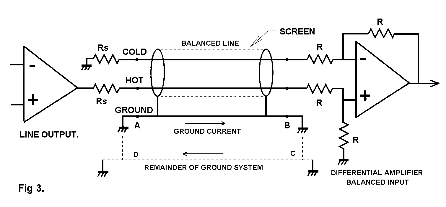
Ground voltages coupled in through the common ground impedance; often called “common-impedance coupling” in the literature. This is the root of most ground loop problems. the equipment safety grounds cause a loop ABCD; the mere existence of a loop in itself does no harm, but it is invariably immersed in a 50 Hz magnetic field that will induce mains-frequency current plus odd harmonics into it. This current produces a voltage drop down the non-negligible ground-wire resistance, and this once again effectively appears as a voltage source in each of the two signal lines. Since the CMRR is finite a proportion of this voltage will appear to be differential signal, and will be reproduced as such. The most common cause of ground-loop current is the connection of a system to two different “grounds” that are not actually at the same AC potential
49 Comments
Twisted pair RCA cables again « Tomi Engdahl’s ePanorama blog says:
[...] get rid of the noise that is coupled as common mode noise to the twisted pair. In systems that use Balanced Line Technology the twisted pair cable construction combined with differential receivers and signal sources make [...]
Value Trendsetter 30 says:
Speaking of reviewing the content numerous will like this because it’s real and it’s good reading from an author that’s writing it for us to read
Tomi Engdahl says:
Differential Signaling: Designing for Long, Fast, or Noisy Applications
https://www.youtube.com/watch?v=DivVHJD_1Lg
This video is your intro to Differential Signaling: Go faster, further.
Bil Herd has covered single-ended topics like TTL, and CMOS, but when increase the speed or distance a signal needs to travel, Differential Signaling is key. This is why it is used in many modern standards like LVDS, CML, and LVPECL
Tomi Engdahl says:
Cable shields
http://www.edn.com/electronics-blogs/living-analog/4442166/Cable-shields?_mc=NL_EDN_EDT_EDN_analog_20160609&cid=NL_EDN_EDT_EDN_analog_20160609&elqTrackId=a7a526f434524aaebcb0179099f4f145&elq=67fb6fd9fb344b108c38beed0e9d229a&elqaid=32603&elqat=1&elqCampaignId=28476
Of the different choices that are available for grounding a shield braid that encloses a differential pair of signal wires, please consider that the shield braid be grounded only at the signal source, at the input end, and not at the output end.
As a first thought, and as something that is often advocated, grounding a shield at both ends may result in severe ground loop currents which could adversely impact EMI and isolation properties.
As a second thought, with the shield grounded only at the output end
the interground interference signal, Enoise, can induce a differential noise signal between the two outputs E1 and E2 that feed the differential amplifier
As a third thought, grounding the shield only at the input end averts both the ground loop problem and the time constant mismatch problem.
Enoise as a common mode signal so that no differential voltage is created between E1 and E2. The A2 differential amplifier is thereby protected from Enoise.
Tomi Engdahl says:
https://en.wikipedia.org/wiki/Balanced_audio
https://en.wikipedia.org/wiki/XLR_connector
Tomi Engdahl says:
https://en.wikipedia.org/wiki/Balanced_line
Tomi Engdahl says:
The balanced line technology is also applicable to many other fields than audio as well:
- Ethernet over twisted pair wiring uses balanced line technology
- video over twisted pair technology convert video signals to balanced signal
- wired telephones use long balanced lines
- many interfaces (CAN, USB, RS-485, DMX-512 etc..) use balanced (differential) 2-wire interface
- in electric power transmission, the three conductors used for three-phase power transmission are referred to as a balanced line since the instantaneous sum of the three line voltages is nominally zero
Tomi Engdahl says:
https://ips.org.uk/encyclopedia/balanced-line/
Balanced lines are typically – and quite incorrectly – explained as follows. A signal is split into two equal but antiphase parts in a balanced line driver. These signals are connected to each leg of a pair cable and eventually arrive at a balanced receiver. This device inverts one leg of the signal. In doing so it adds the antiphase signals together to reproduce the original one and also cancels out any in-phase interference signals that may have been induced in the cable en route. Almost all of this is wrong!
The term phase should always be replaced by polarity, since phase implies shifting the signal in time rather than merely inverting it. But balanced lines are balanced irrespective of whether any signal is present and do not require symmetrical signals to operate correctly.
IEC Standard 60268-3 explains the truth –
“A balanced line is a two-conductor circuit in which both conductors … have the same impedance with respect to ground and to all other conductors”.
If the impedance is the same for each leg then the voltage induced across it by interference will be the same, so there will be no difference in voltage between the two: there will be no “differential” interference voltage. Therefore balanced lines are distinguished by their ability to ignore interference and by nothing else.
There is no requirement for each leg to be driven, let alone symmetrically, and polarity inversion is not always used in the receiver – a simple transformer, which is the classic balanced input, cannot invert one signal leg. What is universal in receivers is the ability to sense the line differentially (differential mode) – the difference in voltage between each leg – since this is the distinction between the wanted signal and most interference, which will be common (common mode) to each leg.
Balanced lines are, in effect, extended Wheatstone bridges and the driver, cable and receiver all have a role in maintaining the balance condition.
Poor tolerance resistors or bad contacts at any one point can have severe consequences in damaging the ability of the entire circuit to reject common-mode interference even though this may not be immediately obvious in the handling of the wanted, differential signal. Under some broadcast conditions a 1 ohm common-mode impedance difference can reduce interference rejection by 15-20 dB.
As with so many audio matters balance will vary across the frequency range. Good transformers can maintain their common-mode rejection across a very wide bandwidth but many electronic input circuits lose this ability at higher frequencies and can be very poor at rejecting RF interference.
Most (though not all) electronic inputs cannot “float” – the maximum common-mode voltage is limited to the voltage swing of the line receiver – and large levels of interference may restrict the undistorted dynamic range of programme. Transformer-connected systems can float
Tomi Engdahl says:
https://www.aviom.com/blog/balanced-vs-unbalanced/
Tomi Engdahl says:
SparkFun THAT 1206 InGenius Breakout
https://www.sparkfun.com/products/14002
The SparkFun THAT 1206 InGenius Breakout Board offers an easy solution to adding a balanced audio input to your circuits. The THAT InGenius technology has been designed for high-grade analog line receiving and offers a low distortion and high common mode rejection in real-world audio applications. Each breakout board combines the THAT 1206 IC, its supporting components, and a ¼” TRS (Tip Ring Sleeve) socket. With these powers combined, you will find it very easy to use the input drivers on breadboards and in projects!
SparkFun THAT 1646 OutSmarts Breakout
https://www.sparkfun.com/products/14003
The THAT 1646 OutSmarts Breakout Board offers an easy solution to adding a balanced audio output to your circuits. The THAT OutSmarts technology has been designed as a high-grade analog line driver and offers a low distortion and high common mode rejection in real-world audio applications. Each breakout board combines the THAT 1646 IC, its supporting components and a ¼” TRS (Tip Ring Sleeve) socket. With these powers combined, you will find it very easy to use the output drivers on breadboards and in projects!
The THAT 1646 OutSmarts Breakout and its sibling, the THAT 1206 InGenius Breakout, perform mirror-image signal conversion.
Tomi Engdahl says:
https://www.ranecommercial.com/legacy/note110.html
Tomi Engdahl says:
https://github.com/sparkfun/THAT_1206_Breakout
Tomi Engdahl says:
https://en.wikipedia.org/wiki/Balanced_circuit
1Design of High-Performance Balanced Audio Interfaces
https://sound-au.com/articles/balanced-interfaces.pdf
Tomi Engdahl says:
Behringer DI20 UTRA-DI Duel Direct Box Review
https://www.youtube.com/watch?v=agolp8jBaks
Behringer ULTRA-DI DI20 Review and Look Inside
https://www.audiosciencereview.com/forum/index.php?threads/behringer-ultra-di-di20-review-and-look-inside.9951/
Tomi Engdahl says:
https://audiophilereview.com/audiophile-news/balanced-or-unbalanced-which-is-better/
Tomi Engdahl says:
https://sound-au.com/articles/balanced-io.htm
Tomi Engdahl says:
https://audiosciencereview.com/forum/index.php?threads/article-understanding-digital-audio-measurements.10523/
Tomi Engdahl says:
With balanced signals with decent equipment 500 ft distance is no big issue. I have used over 100 meters long cable runs with balanced analog audio.
When you have audio cable between two different buildings, I would recommend using an audio isolation transfomer on that run, because different building can have somewhat different ground potentials. Worst case without isolation there is potential danger of huge ground loop noise, electrocution and even fried audio cable / equipment.
Tomi Engdahl says:
Mixing balanced and unbalanced audio
https://www.youtube.com/watch?v=xFHB1LiLwaU
Tomi Engdahl says:
Discussion from https://www.facebook.com/groups/517919938413134/permalink/1654766964728420/
Some studio guys prefer unbalanced. They claim the differential circuit alters the sound. Use quality cables and you should be fine as people have said.
That’s a new one, I’ve never heard anyone say they prefer the tone of unbalanced.
The only downside of balanced inputs are that the Johnson Noise tends to be very slightly higher than an equivalent unbalanced front end. But when you consider the advantages, like immunity to ground loops, I’d prefer the balanced interface any day of the week
The extra amp stage required for balancing is almost always audible. Many mastering engineers use unbalanced gear for this reason.
I didn’t say I prefer unbalanced to balanced. However, I did read an article once on a mastering engineer who did.
This audiophile article states the same.
Just reporting….
https://audiophilereview.com/audiophile-news/balanced-or-unbalanced-which-is-better/
Tomi Engdahl says:
Understanding Common-Mode Signals
https://www.maximintegrated.com/en/design/technical-documents/tutorials/2/2045.html
Abstract: To understand how common-mode signals are created and then suppressed, you should first understand the interaction of shields and grounds in common cable configurations. The following discussion defines a common-mode signal, reviews the common cable configurations, considers shielded vs. unshielded cables, and describes typical grounding practices. The article discusses methods whereby common-mode signals are created and rejected.
The primary focus of this discussion is on RS-485/RS-422 cables and signals, but the discussion also applies to telephone, audio, video, and computer-network signals.
Tomi Engdahl says:
Common Mode Analysis of Ethernet Transformers
https://www.researchgate.net/publication/245513121_Common_Mode_Analysis_of_Ethernet_Transformers
In this letter, a distributed model for Ethernet transformers subject to common mode signals is developed. Explicit formulas for transfer functions are derived and illustrated by numerical examples.
Tomi Engdahl says:
Balanced vs. Unbalanced audio
https://www.youtube.com/watch?v=PzEmKPTb18g
Have you ever wondered what the differences are between the RCA single-ended connections and the XLR balanced connections in audio? PS Audio CEO and founder Paul McGowan shares with us the what’s, whys and wherefores of this subject.
Why don’t more preamps have XLR?
https://www.youtube.com/watch?v=XjiWv0ROjz0
Tons of source equipment have both XLR and RCA outputs but very few preamps have more than one XLR input. Why is that? It just doesn’t seem to make sense.
Tomi Engdahl says:
Balanced vs Unbalanced Audio | Do Balanced Cables Sound Better?
https://www.youtube.com/watch?v=rgfZb1pEIrU
What’s the difference between balanced and unbalanced audio? Does balanced audio sound better? Which cables do you need? XLR, TRS, TS, RCA? In this video, you’ll learn how balanced audio works and hear a demonstration of balanced vs unbalanced audio quality!
0:00 – Introduction
0:22 – Why Use A Balanced Audio Connection?
1:00 – Balanced vs Unbalanced Audio: Cable Construction
1:38 – What Is A Balanced Circuit?
2:21 – Balanced Audio Explained
4:39 – A Common Myth About Balanced Audio
5:17 – Demonstration – Balanced vs Unbalanced Sound Quality
6:07 – Subscribe To Audio University!
Balanced vs Unbalanced Audio | Does Balanced Audio Sound Better?
https://audiouniversityonline.com/balanced-vs-unbalanced-audio/
In this post, we’ll take a look inside some common audio cables to see how they work. I’ll also explore a widespread misconception about balanced audio and demonstrate how big of a difference balanced connections actually make.
But if this is our first time meeting, my name is Kyle. Welcome to Audio University!
What Is Balanced Audio?
Balanced audio is a method of connecting audio devices that eliminates noise. Any noise picked up by the interconnecting audio cable is equal in both conductors (a common-mode signal), and is therefore cancelled out at the differential input device. To fully cancel noise, both conductors of the interconnecting cable must have equal impedance.
Why Use Balanced Audio?
There are many ways noise can enter an audio signal chain. One of the most common sources of noise is other electronic devices.
The currents flowing through any electronic device will form a magnetic field that could induce currents onto nearby circuits.
We are really very lucky to have the cable technology we have today to help prevent this noise from ruining our recordings.
Balanced vs Unbalanced: Audio Cable Construction (XLR, ¼-Inch TRS, ¼-Inch TS, RCA)
When connecting audio components together, you’ll most likely be using one of these cables: XLR, ¼-inch TRS, ¼-inch TS, and RCA.
The XLR and ¼-inch TRS cables both contain a shield, a positive, and a negative. The ¼-inch TS and RCA cables contain a positive and a shield (or ground).
The cable construction will be important in order to understand why the first two cables can support balanced connections and the second two cables cannot.
What Is A Balanced Circuit?
In the book, Handbook For Sound Engineers, Bill Whitlock shares this definition:
A balanced circuit is a two-conductor circuit in which both conductors and all circuits connected to them have the same impedance with respect to ground and to all other conductors. The purpose of balancing is to make the noise pickup equal in both conductors, in which case it will be a common-mode signal that can be made to cancel out in the load.
Ott, H., cited in Bill Whitlock, Handbook For Sound Engineers, p.1185
Differential-Mode Signal
A balanced receiver uses a differential device, which will only respond to the difference in voltage between the two wires of the interconnecting cable.
Common-Mode Signal
If there is an identical voltage on each wire, they will cancel out in the differential device.
There are two important details about the cable that make this noise cancelation possible.
First, both wires need to have the same impedance – that way the strength of the noise voltage that is created is equal in both wires.
Second, the wires need to be the same distance from the noise source – again, so that the strength of the noise voltage is equal in both wires.
We can clearly see that the wires in the XLR and TRS cables are identical. Given that the impedance of a wire varies based on its size, this suggests that the wires in the XLR and TRS cables have equal impedance.
The wires are twisted in the XLR and TRS cables. This helps ensure that the wires occupy the same average position over the length of the cable so that any noise from nearby electronics will be equal in both wires.
Therefore, only the XLR and TRS cables will provide a complete cancellation of noise when connected to a differential input device.
Sometimes an equal but opposite audio signal will be sent across each wire. While this has some additional advantages, it isn’t at all necessary for a balanced connection.
Take a listen to this recording to hear the difference. You might be surprised at just how effectively a balanced audio connection can cancel noise!
Keep in mind that the box of wire isn’t especially close any electronic devices. The random RF (radio frequency) noise that surrounds us everywhere we go is generating most of the noise that you hear in the unbalanced recording.
Do I Need Balanced Or Unbalanced Cables?
OK, so 1000 ft. cables might be a little extreme… How important are balanced audio connections in more practical situations?
The truth is that a balanced connection is always superior to an unbalanced connection. However, for cable lengths under 25 to 30 feet, unbalanced cables offer acceptable audio quality for most applications.
If you’re only running a signal over a short distance, you can most likely use unbalanced cables without much worry. For longer cable lengths, it’s well worth it to leverage balanced audio with an XLR or TRS cable.
Tomi Engdahl says:
Balanced vs Unbalanced Audio | Do Balanced Cables Sound Better?
https://www.youtube.com/watch?v=EeKT4yD3UX4
What’s the difference between balanced and unbalanced audio? Does balanced audio sound better? Which cables do you need? XLR, TRS, TS, RCA? In this video, you’ll learn how balanced audio works and hear a demonstration of balanced vs unbalanced audio quality!
Tomi Engdahl says:
https://www.facebook.com/groups/517919938413134/permalink/1877050505833397/
Can you wire a balanced out to an unbalanced in if you have to?
Yes, it is easy, however, you loose the benefit of balanced transmission.
Balanced output is just two “unbalanced” ouput with a special condition: one output caries the signal, the other is the same, except, it is inverted (multiplied by -1).
—For usual electricaly balanced:
So, you have to connect ground as usual, and take “in-phase” output, and connect to unbalanced signal input.
—For ground independent transformer output and ‘servo-balanced’ electrical output you need to connect ‘inverted output’ to ground beside above one.
Like XLR.1 -> TRS.S, XLR.2 -> TRS.T, and in case XLR.3 -> TRS.S too.
Certainly you need to specify the devices (type) for more detailed infos.
Tomi Engdahl says:
OpAmp basics: balanced to unbalanced signal with difference amplifier
https://community.element14.com/technologies/test-and-measurement/b/blog/posts/opamp-basics-balanced-to-unbalanced-signal-with-difference-amplifier-699051511
Tomi Engdahl says:
https://en.wikipedia.org/wiki/Star_quad_cable
Star-quad cable is a four-conductor cable that has a special quadrupole geometry which provides magnetic immunity when used in a balanced line. Four conductors are used to carry the two legs of the balanced line. All four conductors must be an equal distance from a common point (usually the center of a cable).
Star-quad cable typically provides a 10 dB to 30 dB reduction in magnetically-induced interference.
When star-quad cable is used for a single balanced line, such as professional audio applications and two-wire telephony, two non-adjacent conductors are terminated together at both ends of the cable, and the other two conductors are also terminated together. Interference picked up by the cable arrives as a virtually perfect common mode signal, which is easily removed by a coupling transformer or differential amplifier. The combined benefits of twisting, differential signalling, and quadrupole pattern give outstanding noise immunity, especially advantageous for low-signal-level applications such as long microphone cables, even when installed very close to a power cable. It is particularly beneficial compared to twisted pair when AC magnetic field sources are in close proximity, for example a stage cable that can lie against an inline power transformer.[
The disadvantage is that star quad, in combining two conductors, typically has more capacitance than similar two-conductor twisted and shielded audio cable. High capacitance causes an increasing loss of high frequencies as distance increases.[
Tomi Engdahl says:
The Importance of Star-Quad Microphone Cable
https://benchmarkmedia.com/blogs/application_notes/116637511-the-importance-of-star-quad-microphone-cable
Tomi Engdahl says:
Star Quad Transmission Line Calculator
https://hamwaves.com/zc.star_quad/en/index.html
Tomi Engdahl says:
Why is Star Quad Cable so Effective at Reducing Noise?
Updated on
May 18, 2022
https://audiointerfacing.com/star-quad-cable/
Star quad cables are effective at reducing electromagnetic interference due to their unique construction, featuring a star-like configuration of four (quad) conductors. They are favored in many professional audio settings. They have two main drawbacks, however—their high capacitance levels, which can be an issue for longer cable lengths, and their high cost.
Tomi Engdahl says:
https://audiointerfacing.com/star-quad-cable/
Why is a higher capacitance an issue?
A high-capacitance cable can result in a greater high frequency loss in long cable runs (such as 60-80 feet or longer).
When using dynamic microphones, such as the popular Shure SM57, for instance, a thousand feet of star quad cable can result in the high frequency bandwidth being limited to around 15 kHz—this is 5 kHz below the generally accepted frequency threshold of human hearing.
When using condenser microphones that include internal amplifiers, high cable capacitance can cause distortion. If the internal amplifier has a limited output current, it will clip high-level, high-frequency signals such as vocal sibilance or a cymbal crash.
Hence, if you’re using long cable runs in your setup, you’ll need to carefully consider the capacitance implications of using star quad cable.
Star quad cables are engineered to higher standards than regular cables and this comes at a cost—star quad cables are nearly always more expensive than comparable twisted pair cables, sometimes considerably more.
So, is it worth paying more for star quad cable?
It depends on your usage and how important interference reduction is for you.
Hugh Robjohns, a veteran audio technician and contributor to the industry-leading Sound on Sound magazine, says:
With [a short] cable run, and in a domestic situation, interference isn’t likely to be an issue at all. There’s no reason not to buy star quad if you can get a good deal, but I wouldn’t seek it out specially, as you’re very unlikely to gain any significant benefit.
Hugh Robjohns
As with most purchase decisions, there’s a cost-benefit trade-off to consider when it comes to star quad cables.
Two popular shielding types are foil and braided shielding. Of these, braided shielding performs better and is stronger than foil shielding, hence it is the preferred shielding in high quality star quad cables.
To reduce magnetic interference, the star quad configuration plays an important role.
Star quad cables can result in a 10-30 dB reduction of magnetic interference—far in excess of twisted pair cables.
This level of interference rejection means that star quad cables are particularly useful in situations where cables run close to other equipment, power sources, or other cables.
An example of a well-constructed star quad cable is the Canare L-4E6S. This cable features specialized insulation, durable fillers, and densely braided shielding in addition to its star quad configuration.
Tomi Engdahl says:
Balanced to Unbalanced Conversion the Right Way
https://www.youtube.com/watch?v=jut2WcytHtw
Simple balanced to unbalanced audio converter box DIY.
https://cinemag.biz/line_input/PDF/CMLI-600-600C.pdf
Tomi Engdahl says:
RCA vs. XLR – Is there a SOUND QUALITY difference? Let’s find out!
https://www.youtube.com/watch?v=kkjY8_ob25w&t=1062s
Mixing balanced and unbalanced audio
https://www.youtube.com/watch?v=xFHB1LiLwaU
Tomi Engdahl says:
Does XLR Make a Difference over RCA for Short Distances?
https://www.youtube.com/watch?v=k8FdsG8K6fw
Tomi Engdahl says:
Soldering XLR
https://www.youtube.com/watch?v=gtlEUDyPdx0
Tomi Engdahl says:
Q: Can you use dmx cables for PA speakers
For amplifier to speaker connection the answer is no. Typical DMX cable is very thin meaning lots of resistance. Trying to push considerable power through it will cause it to heat, possibly to point where it melts and catches wire.
Using that DMX cable to carry the line level signal from mixer to powered speaker would most probably work OK.
Q: or not i know it’s not recommended for mics due to higher impedance
The impedance is not a problem here. The DMX cable is shielded 110 ohms twisted pair. Around 110 ohms cable is often used and installed for modern mic and line connections. Around 110 ohms is right impedance for several AES digital audio interfaces and analog audio (has even lower high frequency loss at long runs at high frequencies than lower impedance traditional cable).
The question on DMX cable compared to traditional mic cable is how well it is shielded (good enough for application?). If it is moved during use does generate cinsiderabe moving noise and how well it mechanically can withstand moving a lot.
Tomi Engdahl says:
History Lesson: 600 ohm balanced line
https://groups.google.com/g/rec.audio.pro/c/orbYw-z7JRs
disto…@yahoo.com wrote:
> Hello Everyone,
>
> I am looking for a Greybeard of sorts. I have recently been thrown
> into the audio realm, particularly testing with semiconductor PA’s,
> and I am curious to know where the 600 ohm impedance originated from.
An old telephone standard.
> For example, most testing I have done is with 4 ohm to 8 ohms with
> PA’s and 16 ohms or 32 ohms with headphones for portable audio
> (computing, MP3, cell phone) and there is generally no need for
> impedance matching.
A more correct term might be power matching. When you have a device
with an output impedance, such as the plate of an electron tube, it
becomes important to match the impedances so that you get greatest power
transfer. Best power transfer is when output impedance matches input
impedance. The drawback is that half the voltage is lost. Search on
the term “Thevenin’s equivalent”.
> I have managed to piece together some basic information from multiple
> Google searches that 600 ohms originated from the POTS and was adopted
> by the pro audio crowd decades ago, but I would like some more
> ‘historical’ information of when, why, and how.
Correct and I don’t know the details.
> What prompted this question is that another group uses an HP 8903B
> which has either a 50 ohm or 600 ohm impedance to test audio analog
> CMOS switches and 600 ohms is selected for THD+N measurements.
> The philosophy of the impedance difference intrigued me and thus has
> lead me on a search to understand where the 600 ohms standard came
> from and why some equipment only has this option.
> Any tips, notes, or thoughts will be greatly appreciated.
Apply Thevenin’s equivalent on a circuit with a 50 ohm output impedance
and a 10K input impedance and things look a whole lot different. As the
load is greater than ten times the output, that system is called ‘equal
voltage transfer’ as opposed to a power matched system.
One would have to have a very gray beard
From http://www.sizes.com/units/decibel.htm
“The reference level is 1 milliwatt across an impedance of 600 ohms. The “m”
stands for milliwatt. The 600 ohms came from standards in the telephone
industry, the technology of the early 20th century, in which maximizing
power transfer by matching output and input impedances was an important
consideration. Note that a 0 dBm signal in a circuit with an impedance of
600 ohms corresponds to 0.775 volt rms. A signal change of -3 dBm is about a
halving of the power.
See also volume unit.”
Practically every university science library with a strong engineering
school has all the volumes of the Bell System Journal. It provides a journey
through time, before the era of Lee DeForest, up to the development of what
was quaintly called “LSI” integrated circuitry. I once measured the shelf
space of the Journal; I can’t remember the exact number, but I imagine it to
be around 30 feet. It’s worth a trip to a library.
The matched 600 ohm lines are important for phones because the lines
are so long. When the load is mismatched power bounces and reflects
back the way it came. the result with a cable that stretches across a
country is an echo, which is mighty off-putting. So a minimum matching
standard was imposed, which restricted the amplitude of echoes to an
acceptable level. On long lines echo becomes a problem long before any
mismatch power loss matters.
> I am curious to know where the 600 ohm impedance originated from.
Others here will have better detail, but it’s the “characteristic
impedance” of conductors spaced a couple inches apart in free air.
Characteristic impedance is the resistive value that an infinitely
long line would look like. Another way to describe it is that it’s
the resistive load applied to that not-infinitely-long line that makes
it look like a resistor (and, of that value).
Good point, it’s “ladder line”, http://en.wikipedia.org/wiki/Ladder_line .
But since telephony audio was never transmitted over ladder line, it seems
they picked 600 ohms as a standard audio impedance simply because it was a
number they knew.
>But since telephony audio was never transmitted over ladder line, it seems
>they picked 600 ohms as a standard audio impedance simply because it was a
>number they knew.
Two conductors in free air with an occasional spacer at a coupla
inches is about 600 Ohms.
It wasn’t so much arbitrarily chosen as mandated by fundamentals.
Kinda like the World is 73 Ohms, but different!
Bare conductors spaced a few inches apart and hung from
*telephone poles*. That was the technology for long-distance
lines back before plastic-insulated multi-conductor cable came
into use. At audio frequencies (vs. RF) it is essentially “ladder-
line” and had the 600-ohm characteristic impedance.
wrote in message
news:e946b299-92c7-4990…@p4g2000vba.googlegroups.com…
> I have managed to piece together some basic information from multiple
> Google searches that 600 ohms originated from the POTS and was adopted
> by the pro audio crowd decades ago
Actually, at the time the standard was adopted, the pro audio crowd *was*
the POTS people, at least as far as electrical stuff was concerned. Nobody
but the phone company was doing electrical things with audio. The phonograph
recording world was entirely acoustical.
Later on folk began messing with electrical audio for other things, like
sound films, radio broadcasting and recordings. Much of that work was done
by Western Electric and Bell Labs, both branches of the monopoly AT&T,
better known as Bell Telephone Co..
A lot of audio equipment adhered to the phone company standard because it
had to; radio stations, for example, linked master control to the
transmitter by leased phone lines, so the consoles that drove the lines had
to match the telco standard, and so did the inputs to the transmitters at
the station. It was possible to make gear for internal studio use which
wasn’t telco-compatible, but practically nobody did, because that would
limit its applicability, particularly if the station’s console was all 600
ohm in and out for telco compatibility.
It was really the 1970s before pro equipment began to be built to a
different standard.
Peace,
Paul
>I am looking for a Greybeard of sorts. I have recently been thrown
>into the audio realm, particularly testing with semiconductor PA’s,
>and I am curious to know where the 600 ohm impedance originated from.
If you have open-wire transmission lines with two 18 ga. wires about
five inches apart on the telephone pole, you have a line with a 600
ohm characteristic impedance. This was the standard telephone circuit
well into the 1920s, and as a result the phone company adopted 600 ohm
lines and termination for almost everything.
A sidelight: 20 ga twisted pair with thick cotton insulation tends to
be around 150 ohms characteristic, so the phone company also used that
as a standard, starting in the teens. For many years, CBS Radio used
150 ohms as their transmission line standards, so their equipment would
not interoperate with the rest of the industry without adding more
matching transformers. A lot of gear still had 150 ohm taps well into
the seventies.
>For example, most testing I have done is with 4 ohm to 8 ohms with
>PA’s and 16 ohms or 32 ohms with headphones for portable audio
>(computing, MP3, cell phone) and there is generally no need for
>impedance matching.
Right, in the modern world almost everything has a high-Z input and a
low-Z output, and you don’t care about the cable characteristic impedance
unless you are running cables for tens of miles (as the telcos do).
> You want goofy, look up where the 50 and 75 ohm transmission line
> standards came from…
That’s not goofy. The impedance of free space is (about) 75 ohms, as
is, not accidentally, the impedance of a matched dipole antenna.
The minimum loss of a coaxial transmission line with air insulation
occurs at 75 ohms (for the same reason!) while the minimum
loss for a coax line with plain polyethylene insulation is at
50 ohms approximately. Foam insulation line is intermediate.
It is a pain in the butt that TV (cable and receiving antennas) uses 75 ohm
lines while almost all other RF electronics equip
>That’s not goofy. The impedance of free space is (about) 75 ohms, as
>is, not accidentally, the impedance of a matched dipole antenna.
>
The impedance of free space is 377 ohms (120 pi)
>The minimum loss of a coaxial transmission line with air insulation
>occurs at 75 ohms (for the same reason!) while the minimum
>loss for a coax line with plain polyethylene insulation is at
>50 ohms approximately. Foam insulation line is intermediate.
>
Minimum loss (at which copper loss and dielectric loss cross) comes at
about 67 ohms. There are cables at that impedance, but I’ve never seen
one.
Copper loss dominates at frequencies below about 1 GHz for most
standard cables.
For a given outer diameter Foam cable has lower loss because the lower
dielectric constant allows the cable to have a larger center conductor
therefore reducing the copper loss. It is not because the dielectric
losses are lower. This is a common misconception.
Dielectric losses are not an issue for most cables below microwave
frequencies.
http://www.epanorama.net/documents/wiring/cable_impedance.html
> The minimum loss of a coaxial transmission line with air insulation
> occurs at 75 ohms (for the same reason!) while the minimum
> loss for a coax line with plain polyethylene insulation is at
> 50 ohms approximately. Foam insulation line is intermediate.
75 ohms answers the question “what impedance has the lowest attenuation
per unit length for a given outside diameter?”. I believe that is true
*regardless* of the dielectric.
The fact that 75 ohms (and 300 ohms) are antenna impedances is
convenient, but not the main reason for the prevalence of 75 ohm cable
– the preponderance of antennas are vertical quarter-wave devices, and
those run around 50 ohms.
50 ohms (sort of) answers the question “what impedance has the greatest
power handling capacity for a given outer diameter?”. I believe that is
true *regardless* of the dielectric.
The precise answer is around 37 ohms, but the curve is very broad, and
50 (or 51.5 or 52) ohms is useful for (vertical) antennas, so that’s the
impedance cable is built to. Incidentally, the lower DC resistance of 50
ohm cable made it the best choice for Ethernet (over 75 ohm’s lower
attenuation) because it makes collision detection work better.
Propagation delay limits the length of an Ethernet segment anyhow, and
that doesn’t vary greatly with impedance.
> It is a pain in the butt that TV (cable and receiving antennas) uses 75 ohm
> lines while almost all other RF electronics equipment is 50 ohm.
I suspect that the length of coax in use for cable TV RF plus baseband
video far, far exceeds all other uses of any other impedance of cable,
and in those uses, low transmission loss is more important that anything
else. Plus, of course, the major antenna type used for TV is the
(folded) dipole, which, at 300 ohms, has an impedance that is
“convenient” for use with 75 ohm coax.
“Soundhaspriority” wrote in message
news:ELWdnbAlZoKUU4TX…@giganews.com…
Yes I have a gray beard, Nobody here remembers when telephone poles had
cross arms with green or clear glass insulators, yes open wire pairs, multi
pair cable hadn’t been perfected yet, the last few places that used open
wire were the railroads for signals and com. the phone company started
frequency multiplexing on open wire lines 12 channels on 2 pairs just in
time for WWII. we have come a long way in a short time, not everybody had
telephones back then usually the rich and the Doctor and the sheriff, had 8
party lines too. Very few trunk lines between cities, it would take hours
to set up a long distance call, some of the little companies didn’t talk to
each other at all. It wasn’t exactly ladder line but the wires were
stretched tight enough they never crossed and stayed equidistant,
occasionally there would be a mid span cross-over device to minimize
crosstalk on the multiplex. I started with Bell Tel in 1970, my observation,
new technology is built on old, you have a system of standards in place that
works and everyone has in common. All of our program audio ckts were 600
ohms, all of the test sets were 600, 900, or 1200 ohm impedance, for 19 or
22 or 24 or 26 gauge wire. When I was in the Navy I noticed the military had
an affinity for 500 ohm ckts ?? another convention. For Bell it was all
defined in the Bell System Practice, It said what and how and how often, if
you didn’t follow the practice you could get a day off or fired. 0 dbm at 1
kHz into 600 ohms = 1 milliwat, I’m not going to complain it works for me.
Best regards,
David____________
Audio and music are related but by no means the same thing. Hell, lots of
people do plenty of fine audio work that involves no music at all, just
dialogue and talking head stuff.
Tomi Engdahl says:
https://www.soundonsound.com/sound-advice/q-what-ground-compensated-output-my-mixer#amp_tf=L%C3%A4hde%3A%20%251%24s&aoh=16768330588369&referrer=https%3A%2F%2Fwww.google.com&share=https%3A%2F%2Fwww.soundonsound.com%2Fsound-advice%2Fq-what-ground-compensated-output-my-mixer
Tomi Engdahl says:
https://www.sweetwater.com/insync/what-is-the-difference-between-a-balanced-and-a-ground-compensated-output/
Tomi Engdahl says:
https://en.wikipedia.org/wiki/Balanced_audio
https://www.learningelectronics.net/circuits/balanced-unbalanced-converter-for-audio.html
Tomi Engdahl says:
https://sound-au.com/articles/balanced-io.htm#s4
https://www.learningelectronics.net/circuits/balanced-unbalanced-converter-for-audio.html
Tomi Engdahl says:
https://sound-au.com/articles/balanced-io.htm#s4
http://www.douglas-self.com/ampins/balanced/balanced.htm
Tomi Engdahl says:
https://www.learningelectronics.net/circuits/balanced-unbalanced-converter-for-audio.html
Tomi Engdahl says:
https://sound-au.com/articles/balanced-io.htm#s3
Tomi Engdahl says:
It’s because on the output, it’s an “active balanced” output, meaning + and – outputs are driven by two different opamps each referenced to ground. So by taking just the + output referenced to ground its no different than any unbalanced output. But on the input side + and – connect to non inverting and inverting inputs of the same opamp, you can’t just leave the inverting input floating you have to tie it to a zero reference for the non-inverting input to make sense.
Tomi Engdahl says:
http://www.douglas-self.com/ampins/balanced/balanced.htm
Tomi Engdahl says:
https://coretechgroup.com/dbm-calculator/
Tomi Engdahl says:
https://www.prosoundweb.com/the-pin-1-problem-revisited/