Nowadays the most commonly used microphone types that need power from microphone connector are PC sound card microphones (3.5 mm plug) and Phantom powered professional microphones (XLR connector). Those two microphones are not compatible with each other, but there are cases where you might want to interchange them. In this posting I will describe how to connect PC microphone to professional mixer phantom powered XLR mic input. This is an application I have made few times and I have got questions several times on my mailbox.
Phantom power feeds 12-48V power to both signal wires on the connector as describes in this picture from Belden document Phantom Powered Microphones:
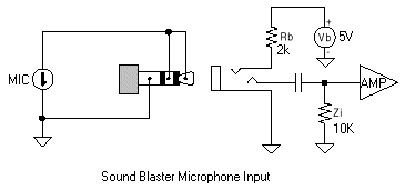
PC microphone feeds lower voltage (typically 3-5V) to ring contact of 3.5 mm jack (similar to plug-in-power PiP). Here is the operation principles of PC sound card microphone interface from my Microphone powering document:
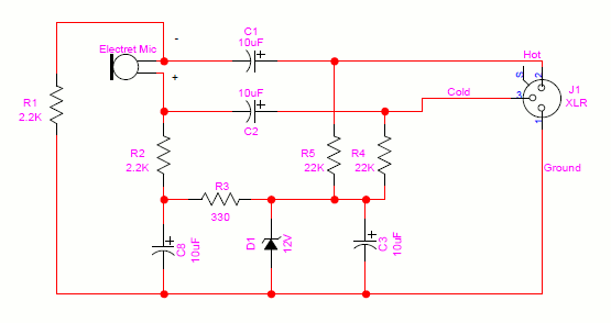
On my Microphone powering document I had provided a “simplest circuit”: very simple method of connecting an electret microphone capsule to the a balanced phantom powered (48V) mixer XLR input.
                     _____
   HOT (2) ---------|_____|------+
                    47 kohm      |+
                                MIC
  COLD (3) ----+              CAPSULE
               |                 |-
GROUND (1) ----+-----------------+
Note that this is a very simple “hack” to interface an electret microphone capsule to a mixer. This circuit works but has it’s downsides like sensitivity to noise in phantom power, unblanced signal transmission (prone to interference) and high output impedance (can’t properly drive long cables). This circuit can be used to test electret capsules connected to mixer using very short cable. The circuit has proven to work with some modern electret capsules and some mixers, but has had some problems. For example some microphones fail to work with this circuit properly (if they take very little current the voltage over them can get too high for them to work).
So something better was needed. The balanced circuits from Microphone powering document are out of question for PC microphone adaptation, because in PC microphones minus side of electret capsule is connected to cable shield, while my balanced adapter circuit needed the electret capsule to be floating (T-power like connection).
Trying to just wire in PC mic with cable to such circuit will cause the circuit to pick up lots of noise! “Better electret microphone phantom powering circuit” and similar designs from Microphone powering document are not suitable for PC microphones or headsets as they are normally wired.
So I needed a “different better approach” to power PC microphones from “P48” or “phantom power 48 volts”.
Some years ago I made a better trick that works with PC microphones which are wired so that tip and ring contacts are shorted together on the mic (quite many microphones have I have are two wire electret capsules wired in this way). I took apart an old adapter I built years ago and had not documented so I can document it now:
I have wired 27 kohm resistor from XLR pin 2 to 3.5 mm plug tip.
I have wired XLR pin 1 to 3.5 mm plug shield/ground.
I have wired 2.2 kohm resistor between 3.5 mm plug tip and shield/ground.
In this hack I had not connected anything connected to XLR pin 3, so maybe it would be a good idea to have there 26 kohm resistor to pin 1 ground.
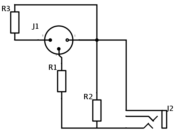
I added that and ended with the following circuit design:
 Drawn with Scheme-it
 R1 = 27 kohms
 R2 = 2.2 kohms
 R3 = 27 kohms
 J1 = 3 pin XLR male
 J2 = 3.5 mm stereo jack
This circuit seems to work well. The voltage divider formed by R1+R2 make sure that the voltage the microphone sees is 4 volts or less (depending on load caused my microphone). The source impedance of the power source is also similar to the circuits in PC sound cards. R1 passes the signal to mixer + pin somewhat attenuated. R3 tries to provide approximately same load to – side of XLR as the + side gets (around same amount of current taken and similar AC impedance to take care of balance).
This circuit has been proven to work pretty well when the adapter was plugged directly to mixer XLR input or though short cable. Due high output impedance it might not be a good idea to use long cable. This circuit has limitation that it only works with PC microphones that have tip+ring directly wired together to two wire electret capsule as shown in Computer microphones web page:
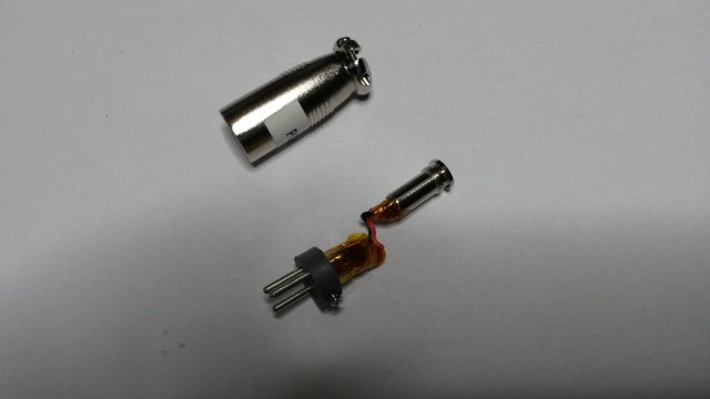
Most of the PC microphones and PC headsets are wired in this way, but maybe not all. All the PC microphones and headsets I had access were wired in this way. You can check with a multimeter if your microphone is wired in the ways: just measure the resistance between tip and ring, it should be zero or almost zero. If that is the case my circuit works with it well. If the resistance is not zero or almost zero, there is no guarantee that things will work out as expected. The circuit can be built so small that it fits inside XLR connector:
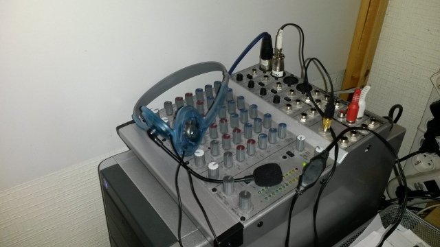
Here is the circuit in use:



33 Comments
paolo gramigna says:
Hi,
I have tried the above circuit, and it works!
But there is a problem: when i connect the mike using this circuit, i get a loud “POP” on the mixer’s output.
I supposed that it comes from the mike when powered.
But when i disconnect the mike, i get another loud “POP” and that’s second POP cannot come from the mike…
Those POP are really annoying.
How can i get rid of them?
thanks for any advice,
Paolo from Italy
Tomi Engdahl says:
Thank you or your feedback on the circuit.
I don’t have any ready solution for POP problem.
lasershark says:
hi. it is standard practice to mute channels/pull down faders/switch off amp and speakers before connecting or disconnecting a phantom powered microphone to a mixer.
Tomi Engdahl says:
Yes it is.
And it is a recommended practice to turn off the phantom power (or whole mixer) when plugging/unplugging phantom powered microphones because some sensitive (not well protected older devices) can be damaged if you plug/unplug with power on.
Raziel says:
Greetings,
I am interested in using a high quality gaming headset for DJing. There seems to be better headsets in gaming than pro-audio.
I would like to know if you have a Digi-Key part number for the resistors you used for the last circuit with 3 resistors.
Your insight is greatly appreciated. Thanks in advance.
Cheers.
Raz
Tomi Engdahl says:
Thank you for your feedback.
Gaming headset market has evolved while it seems that pro audio headset market has not changed that much.
Depending on the different needs I have faced needs to adapt some pro headsets to gaming and
gaming type headsets to pro audio devices.
Unfortunately I don’t have Digi-Key part number for the resistors in the circuit, because I have not bought
those resistors from there and I don’t use Digi-Key to get parts for my circuits (I know Digi-Key, but
I typically source most my parts I don’t have from local components suppliers or directly from china…)
Raziel says:
Sounds good.
Can you provide a bit more detail about the resistors?
27K Ohm (1W? 1/4W?)
2.2K Ohm (Watts)
I just want to be sure to order the right ones. I am really planning to make a few circuits for my pro-audio setup. Any help you can provide would be most appreciated. Thanks.
Cheers.
Raz
Chris says:
Hi Tomi, thank you for these explanations. I want to use a homebrew gooseneck mic w/ XLR connector on my Alesis iO26 interface to talk-back to the musician and realised the circuit with the voltage divider R1-R3 as you described here. It works nearly perfect, but the level and/or gain is too low, the signal is too weak, I have to yell into the mic to get heard. So, my idea is, to build up a little FET preamp, using a BS170 due to it’s high SD-voltage of 60V. But – at the moment – I have no clue how to build it up with the symetrical XLR connector. Do you have any suggestions for this project? Any hint is appreciated!
Thank you very much!
Chris
Tomi Engdahl says:
For stronger signal with my circuit, you could add a suitable capacitors in parallel with R1 and R3.
The capacitor will pass the AC signal while still blocking the phantom power DC on normal operation.
What still needs to be considered is power spike when phantom power is turned on.
For getting more signal to mixer I would consider something like instead of just capacitor, use capacitor + suitable resistor circuit.
I would try something like 10 uF electrolytic capacitor (60V or higher voltage rating, + side to XLR connector) in
series with 2.2 kohms resistor… This should give much stronger signal, depending on mixer designs I would expect to get something
like 10 dB more signal level…
You can also find some more complicated microphone interfacing circuits at
http://www.epanorama.net/circuits/microphone_powering.html
There are several circuit ideas at “Balanced electret microphone circuit”.
Those give stronger signal and well balanced mic output – at expense of more complicated circuit and electret capsule is floating.
Chris says:
Great, works very good, seems more than 10dB! I forgot to mention, all componets must fit into the XLR plug and/or the head of the mic, so (your) other sugestions I was still aware of, but I’m not a SMD Pro Next days I’ll see whether the level is high enough for my guitar player, but I think, it’s gone be ok, otherwise the punishment well be SMD as shown here:
http://www.naiant.com/images/MSH_Kit_Mic.GIF
Thank you!
Jon Blackstone says:
Tom -
I’ve got a solution for this that’s very simple, and is working for me.
I connect the ECM capsule (cheesy computer mic) directly to pins 2 and 3, and just pull pin 3 towards ground (pin 1) with a 47K resistor to create a 6V differential across the ECM.
(2)---------------+

                  MIC

(3)----+----------+

      47K

(1)----+

               (both mic wires insulated from any metal casing)
This avoids attenuating the signal as the 3-resistor scheme does. And I may be mistaken, but I think it’s even roughly “impedance balanced”, as the ECM floats much the way a transformer in a dynamic mic would (the 47K additional loading on one side being negligible).
Am I missing something?
Dino says:
excuse the question, is it possible to have a more detailed diagram for how the connections are? my email is [email protected]
thanks
Tomi Engdahl says:
Sorry I don’t have more detailed drawings to post.
Jon Blackstone says:
(Oops. My little diagram got its spaces stripped out.)
Tomi Engdahl says:
That stripping down of spaces is a feature of this blog system commenting.
I still understood the drawing anyway.
And I think that your idea is a really good idea indeed.
I have to test it.
Tomi Engdahl says:
I tested the circuit and got it working… So the idea works in practice.
Steve R says:
I assume, in Jon’s diagram, the numbers on the left are the XLR pins and the tip goes to XLR 2, ring going to XLR 3 with the 47K between XLR 1 and 3. It’s probably obvious, but I’ve learned not to assume.
T. Keith Bossert says:
I wanted a microphone clipped to my shoelaces for a foot tambourine I use while playing guitar, singing, and playing other percussive instruments with my feet. This circuit worked great. Now with the mic closer to the tambourine I can use less gain, and get higher volume without the feedback I got with a mic on a boom stand pointed towards the tambourine. Thank you for sharing!
Tomi Engdahl says:
Thank you for your feedback.
Tomi Engdahl says:
Can phantom power damage your microphones?
http://avstomusic.blogspot.com/2012/05/can-phantom-power-damage-your.html
Phantom power or +48V DC seems like a high enough voltage to do some serious damage to microphones that don’t need it (like ribbons, dynamics and tube mics). Some people shut phantom power off when plugging and unplugging condenser microphones as well.
Phantom power is usually 48V DC at very low current – (micro amps up to about 10 miliamps).
Tomi Engdahl says:
Phantom Power – How to Avoid Damaging Your Microphones
https://www.youtube.com/watch?v=DZ5AdyreC4o
Phantom power is used to turn on any condenser microphone such as small pencil condenser mics, and large diaphragm vocal microphones. It is important to understand how to properly use these mics, and how to properly apply phantom power to turn on these mics. For more go to: http://www.creativesoundlab.tv
Tomi Engdahl says:
Can phantom power damage equipment that does not need it?
http://www.thefretboard.co.uk/discussion/70513/can-phantom-power-damage-equipment-that-does-not-need-it
Some mixers only have the option to turn phantom power on or off globally rather than on individual channels.
Can sending phantom power to gear that already has its own power supply damage it?
Yes, it can, but only under certain conditions. For example, you have phantom power turned on and use a microphone patch bay and connect up a sensitive ribbon mic and then patch it into that mixers channel. That can damage the mic, although it isn’t common. I’ve never seen any damage to line level gear, the extra current will likely be dissipated as heat.
Anything that is designed to plug into an XLR mic input “should” be designed to cope with phantom power. The problem arises where gear might be adapted to XLR for some reason or, rare these days, a line input on a mixer/preamp retains spook juice because of poor, lazy design.
Most equipment is (or again “should”) be protected, input and output against voltages up to the internal supply rails but 48V is way above that in almost all cases so the moral is. If it is not equipped to go directly into an XLR mic input DON’T DO IT!
It won’t cause a problem with anything that’s been designed properly for balanced audio, as either / or there will be transformer coupling which blocks the DC volts of the phantom or there will be capacitor coupling which does the same.
The main thing is always remember to switch off the phantom power before you plug in or change any leads … because in certain case using jacks rather than XLR’s you can make one contact before another and that can cause problems. Also don’t use any cables which aren’t balanced, some very cheap mic cables have the normal 3 pin XLR connectors but are wired with 2 core wire in an unbalanced format.
Tomi Engdahl says:
The Danger of Applying Phantom Power to Unbalanced Outputs
https://www.sounddevices.com/tech-notes/the-danger-of-applying-phantom-power-to-unbalanced-outputs
Phantom power, however, has the potential to damage equipment not designed for it, specifically devices with unbalanced outputs. Unless the device is designed to accept phantom power, do not apply phantom. Some unbalanced equipment does not have any, or sufficient, protection from DC voltage and its output circuitry can be damaged, requiring repair.
Important Reminders for using Phantom Power
If a single-ended (unbalanced) output device such as a keyboard, consumer tape deck, sound card, or receiver is connected to any balanced preamp, make certain phantom power is turned off on that input. Depending on the design of the device, its output can be permanently damaged if phantom is applied.
When connecting a single-ended (unbalanced) output device to a balanced mic preamp with phantom, use an isolation transformer at the unbalanced device output to be certain that any phantom that may inadvertently be present is isolated.
If connecting to a product which is suspected of having inadequate output protections and phantom power is not defeatable, use a build-out resistor of roughly 1k ohm in the “hot” leg to help mitigate effects of the phantom voltage.
Some balanced output devices, such as T-powered microphones and dynamic ribbon microphones, can be permanently damaged if phantom power is applied to them. Turn off phantom when connecting these types of equipment.
Tomi Engdahl says:
Q. Has phantom power damaged this keyboard?
https://www.soundonsound.com/sound-advice/q-has-phantom-power-damaged-keyboard
Most keyboards have unbalanced instrument or line-level outputs, and a standard XLR-TS (or TRS) lead or adaptor would almost certainly put 48V phantom power directly across the keyboard’s output driver.
Depending on the design of the output stage, that could result in the sound becoming weak and feeble temporarily, or it could result in more serious permanent damage. For example, the 48V phantom could reverse-bias or simply over-volt the keyboard’s output capacitors, causing them to break down and eventually destroy the output stage. And that’s quite possibly what happened to cause the previous internal damage to the keyboard.
So it is absolutely essential to use some form of galvanic isolation between a keyboard (or guitar amp, DJ mixer, or any other electronic equipment) and a phantom-powered mic input, unless you know absolutely for sure that the electronic output is specifically designed to cope with it. A passive DI box is the easiest, cheapest and simplest solution.
Tomi Engdahl says:
Unfortunately, many preamp and guitar-amp manufacturers incorrectly label bias power as “phantom” power—they are not the same thing! However, the difference is usually obvious from the connectors: If you have an amp or preamp that provides power for a mic, an XLR-mic connector almost certainly indicates real phantom power. A system that provides power through a stereo ¼-inch guitar jack generally indicates bias power. The mics are similar—a mic with an XLR connector expects phantom power, a mic with two wires, or a simple non-XLR connector, probably expects bias power.
Source: http://acousticguitar.com/everything-you-need-to-know-about-microphone-phantom-power/
Tomi Engdahl says:
Plug adapter with power converter
TRS Mini-jack (3.5 mm) to XLR 3M
Integrated voltage converter from phantom power (12 – 48 V) to plug-in power (3 – 5 V)
Allows operation of Rode HS2, VideoMic GO and VideoMicro on professional XLR microphone inputs with phantom power
https://www.thomann.de/fi/rode_vxlr_416774.htm
Tomi Engdahl says:
Dangers & Solutions – Audio Phantom Power + Demo
https://www.youtube.com/watch?v=_8UTGcuAtd0
What you should know before turning on phantom power – energize condenser microphones and active DIs
https://www.youtube.com/watch?v=cOL0yOfbTbw
Tomi Engdahl says:
EEVblog #616 – How Microphone Phantom Powering Works
https://www.youtube.com/watch?v=e5xenXTwAzo
Doug Ford, former head designer at Rode Microphones explains 48V phantom powering of microphones and how it works.
There is a ton of stuff here:
Electrostatic and electromagnetic noise, differential amplifiers, common mode noise, transformer magnetisation current, JFET differential driver circuits, balanced impedances, phase splitters, miller capacitance and how it matters, and he explains how the Schoeps amplifier topology works.
Tomi Engdahl says:
DIY electret microphone adapter to XLR phantom power
https://www.youtube.com/watch?v=g-mItyp1_2E
The world’s simplest phantom powered condenser microphone design!
https://www.youtube.com/watch?v=jM2tdXXaa-A
Tomi Engdahl says:
Do electret condenser microphones require phantom power?
https://electronics.stackexchange.com/questions/25229/do-electret-condenser-microphones-require-phantom-power
Tomi Engdahl says:
diy electret microphone, which phantom power adapter?
https://www.soundonsound.com/forum/viewtopic.php?t=76054
Tomi Engdahl says:
https://sound-au.com/articles/mic-electret.htm
Tomi Engdahl says:
https://locusonus.org/wiki/index.php?page=Electret+mics.en