A valve amplifier or tube amplifier is a type of electronic amplifier that uses vacuum tubes to increase the amplitude or power of a signal. In audio applications, valves continue to be highly desired by most professional users, particularly in recording studios’ equipment and guitar amplifiers. Among stereo enthusiasts, there is a subgroup of audio buffs who advocate the use of tube amplifiers for home listening; they argue that tube amplifiers produce a “warmer” or more “natural” valve sound. Tube sound (or valve sound) is the characteristic sound associated with a vacuum tube-based audio amplifier.
Before the rise of the transistor in the 1950s, all amps used vacuum tubes. Still the audible significance of tube amplification on audio signals is a subject of continuing debate among audio enthusiasts. Audiophiles disagree on the relative merits of tube vs solid state amplification. Tube amplifiers have retained a loyal following amongst some audiophiles and musicians. Some musiciansprefer the distortion characteristics of tubes over transistors for electric guitar, bass, and other instrument amplifiers.
Today tubes are the incandescent light bulb of the audio world: an older, relatively inefficient technology that consumes a good deal of energy to output a modest amount of power. For power amplifiers solid state designs can be manufactured without output transformers and are therefore immune to speaker-dependent impedance mismatches and transforer effects. I have been long the person who has usef transistors for hifi applications and considered they to be better for hifi amplifiers.
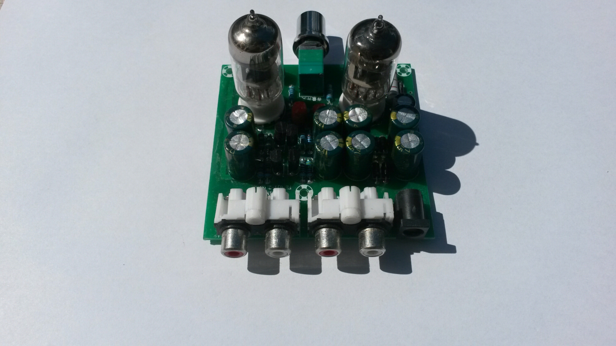
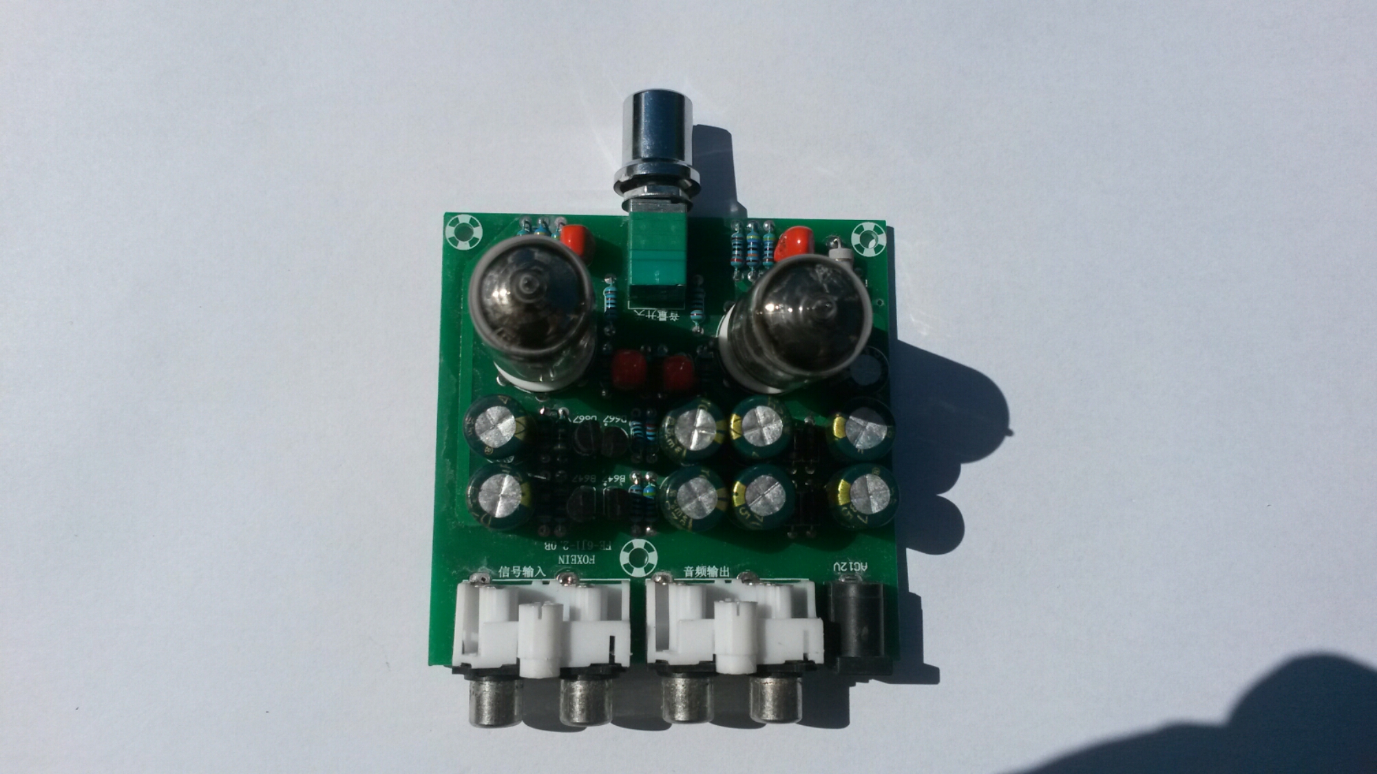
Tubes have their place in audio processing where you want to add to the sound the “warm tube distortion” sound (for example in guitar amplifiers). For preamplifer use tubes can work well. To get the idea of tube sound and how tube preamps works, I got this cheap kit for experimenting: AC12V/1A Stereo 2.0 Pre Amplifier Headphone Module Amplifier Buffer Board. It is a preamplifer that is suitable for conntrolling volume of line level audio signals (attenuate or amplify) and maybe add some magic tube sound to audio. Cheap way though of experiencing ‘tube sound’!
Type: FE-6J1-2.0B
Channel type: 2.0/ stereo
Power input: AC12V 1A / 5.5*2.5 plug
Knob function: Power switch / volume control
Size: 76 x 74 x 20mm
Pre-amp tube diameter: 18mm
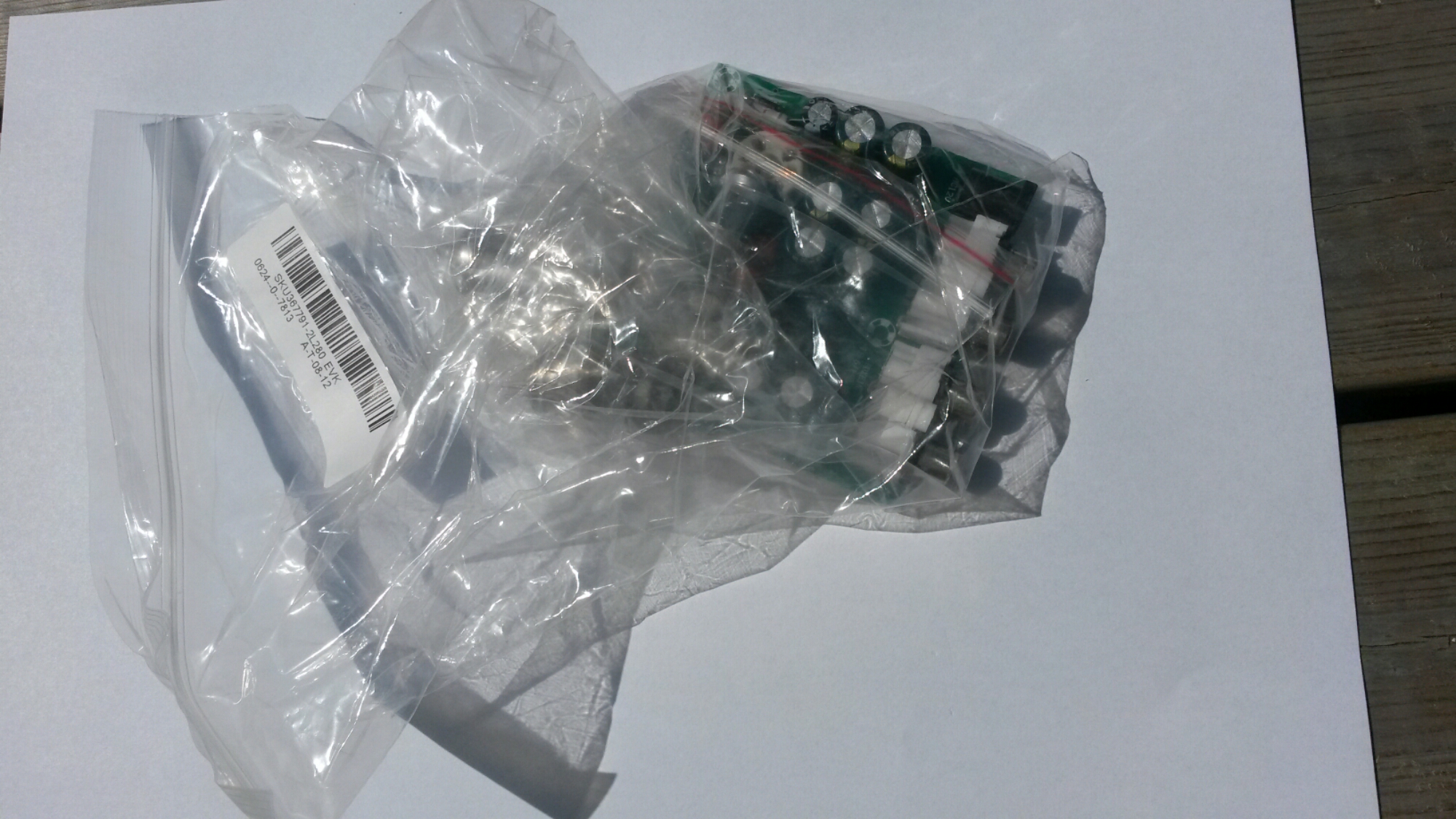
Everything was packed to a plastic bags.
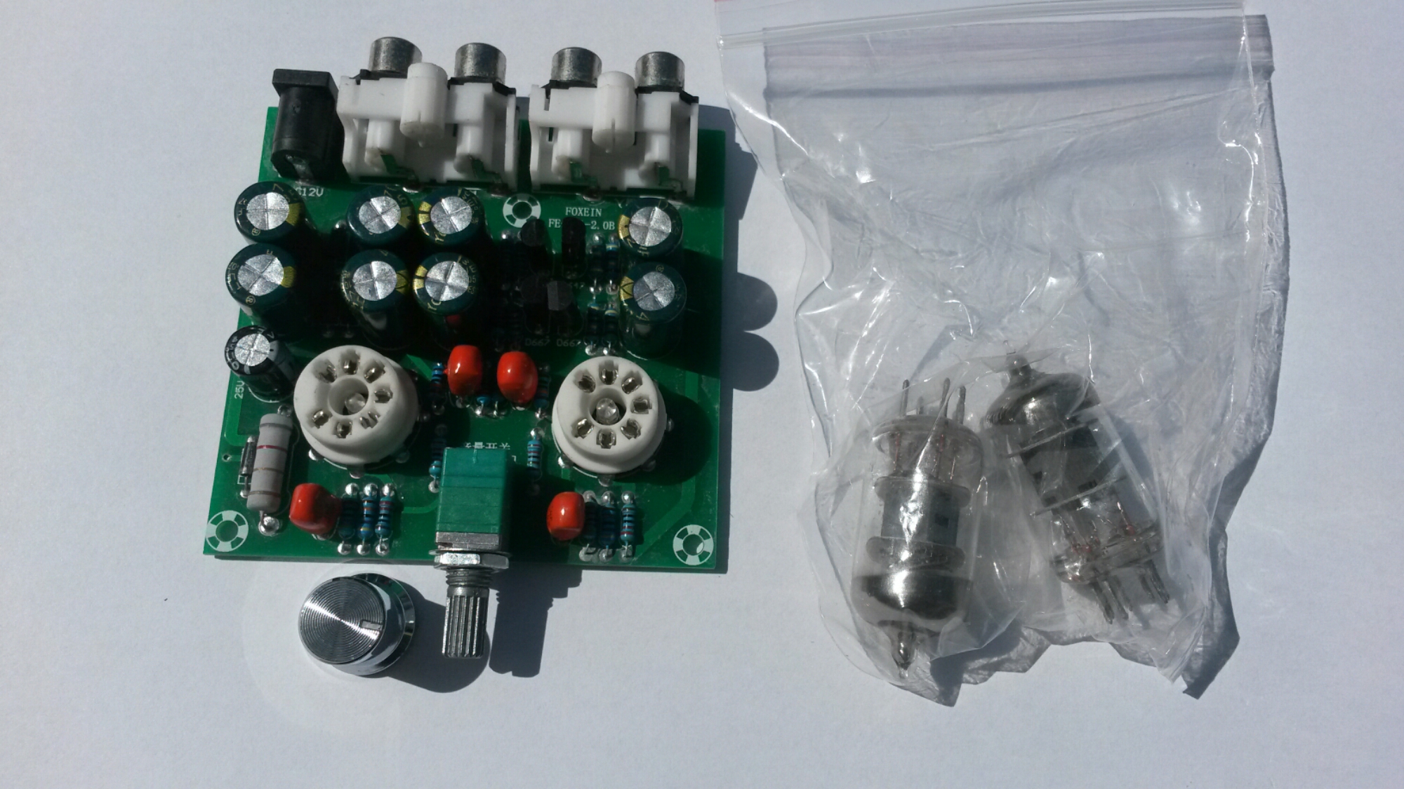
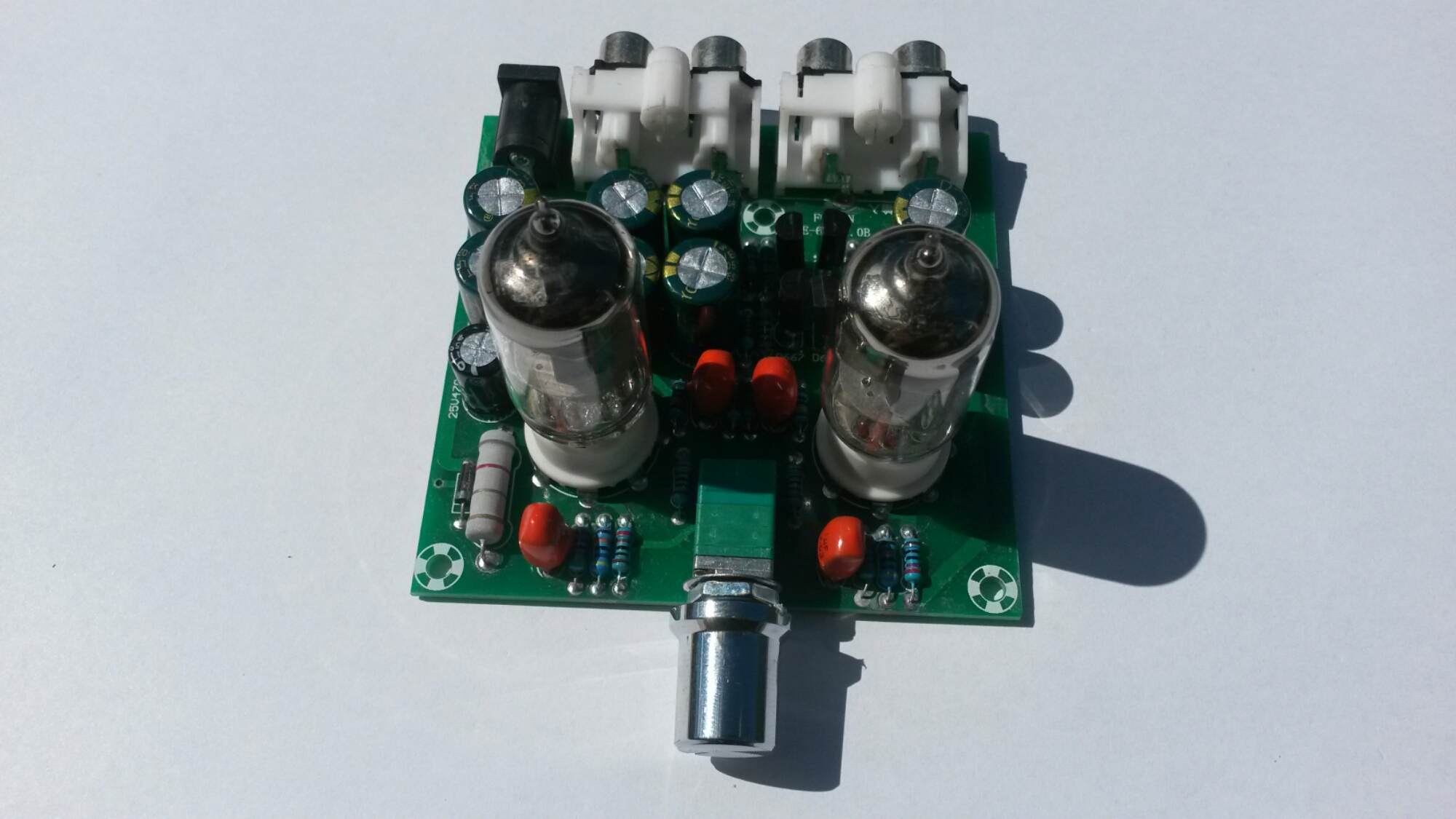
There seem to be some small LEDs in the center of tube sockers. Those are blue LEDs that make the tubes to glow in blue color.
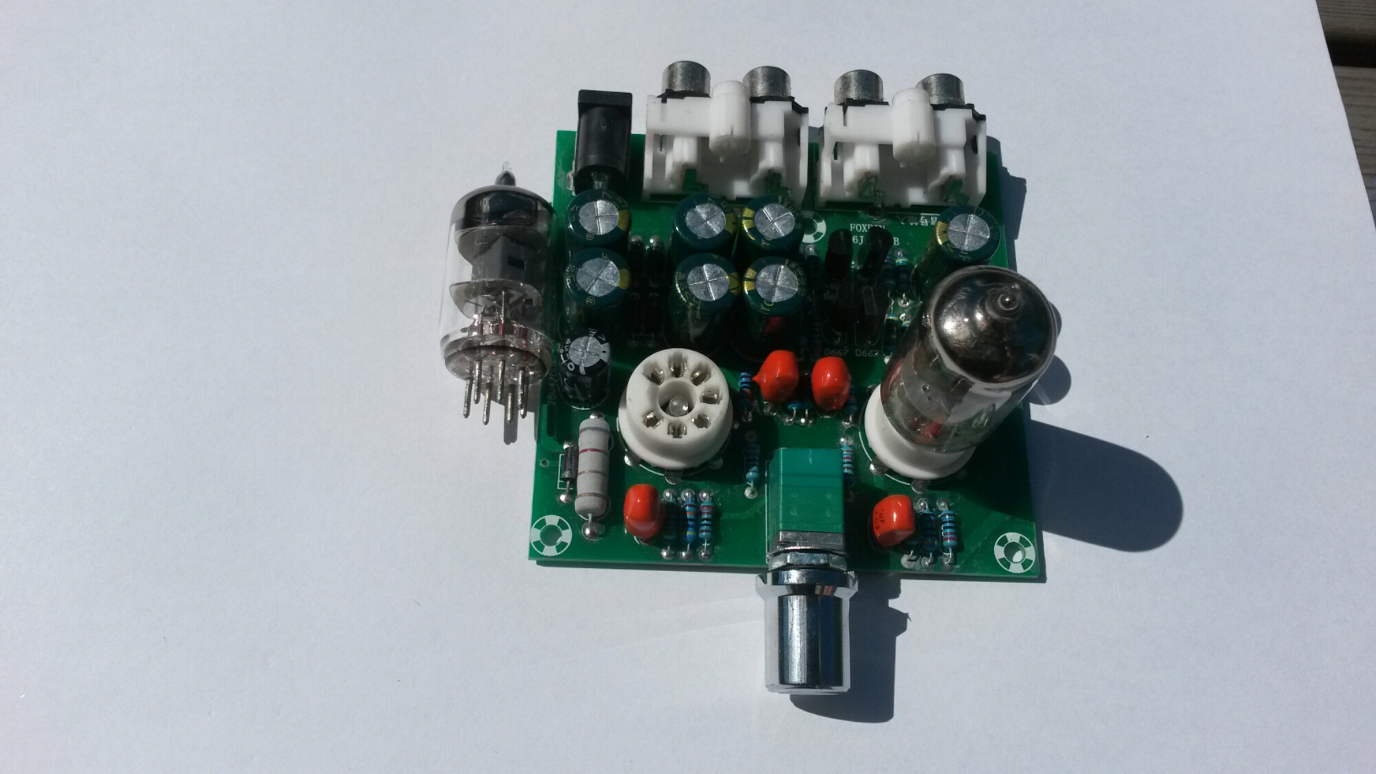
One tube installed.
The volume control in this board is combined volume control and power switch: The knob rotates counterclockwise to reduce the volume, when the volume to the hour, continues to rotate, until the “tick” sound, then power off, lights out.
A look to the connectors…
On the left side: Audio signal input terminals that can be connected to mobile phones, computers, MP3, MP4, and other music player.
On the right side: The output terminal of the audio signal can be connected to an audio signal input terminal of a power amplifier and a power amplifier board. And next to them power input (12V AC 1A).
When I powered the amplifier, it did what it promised. It worked OK as a preamplifier.
Voltage amplification can be controlled from zero to around 6 times (around 15 dB).
The output worked on testing well to over 2Vpp input signal amplitudes at maximum amplitude without noticeable distortion on oscilloscope screen starting to appear.
The signal output impedance is around 3 kilo-ohms. That works well as line level signal preamplifier that drives power amplifier. This circuit is not headphone amplifier that drives headphones (if you thing if that from product name), it would would be pretty non-ideal headphone amplifier for low impedance headphones.
Does what it describes as preamplifier for audio signals. It sounds good, but I can’t find it to be adding any magic “tube sound” to the audio. The circuit adds some slight huming though (at more than about 1/3rd volume).
Note on powering: you need an (not DC) 12V plugpack or transformer. The kit says it needs 12V 1A power supply, so that what I used (I did not measure the actual power this circuit takes).
Ti get better idea how this circuit amplifier works, a circuit diagram would be nice. With some Googling I found that there are several pages that tell about this or very similar tube amplifiers:
https://www.circuitlab.com/circuit/9vnehk/fever-6j1-tube-pre-amp-circuit/
http://www.diyaudio.com/forums/tubes-valves/286349-6j1-tube-buffer-circuit-diagram.html
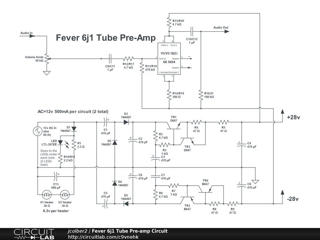
The best circuit diagram I could found was this at https://www.circuitlab.com/circuit/9vnehk/fever-6j1-tube-pre-amp-circuit/
It seems to be mostly correct (shows only one channel), but has some small details that do not seem to be correct (for example connection of resistor on amplifier output should be connected to ground and not -28V). By the way the circuit diagram can be edited at https://www.circuitlab.com/editor/#?id=9vnehk
As you can see in the circuit diagram the power supply part converts the 12V AC input to +28V and -28V power rails that are used to power the tube. This means that the tube is run at 56V voltage (which is quite low voltage for an audio tube circuit, they typically operate at 100-300V voltage depending on tube type). This 56V voltage is good for safety – it does not hurt too much if you accidentally come in contact with this voltage when you test the board before putting it to case.
The power supply circuit consists of voltage multiplier + rectifier circuit followed with filter capacitors, some transistor circuitry (emitter follower with current limiting, somewhat resembles gyrator circuit) and more filter capacitors.
The tube heaters are directly powered from input 12V AC (two 6.3V heating coils in series can be powered from 12V AC).
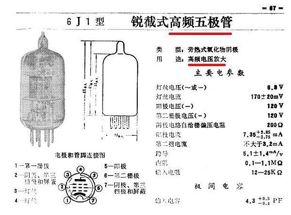
Information on the 6J1 tube used can be found at http://www.radiomuseum.org/tubes/tube_6j1.html and http://greatsound168.pixnet.net/blog/post/254453398-%E4%BA%8C%E5%8F%B06j1%E7%B7%A9%E8%A1%9D%E7%B4%9A%E7%9A%84%E5%88%86%E6%9E%90
Another preamp circuit using 6J1 tube at http://www.yunwt.net/1mydiy/qt14.htm
The basic design of this AC12V/1A Stereo 2.0 Pre Amplifier Headphone Module Amplifier Buffer Board seems to be sensible. If I had designd this I would maybe had designed few things slightly differently (for example power supply filtering and maybe tube heating) – that could have maybe reduced the slight mains humming on the output. Anyways as it isC12V/1A Stereo 2.0 Pre Amplifier Headphone Module Amplifier Buffer Board seems to be good quality cheap tube preamplifier.
312 Comments
Tomi Engdahl says:
How Vacuum Tubes Work
https://www.youtube.com/watch?v=nA_tgIygvNo
edited and annotated the original 28 minute film “Electronics at Work” down to 3.5 minutes. The annotations help explain how electronic vacuum tubes flow electrons to amplify guitar signals and rectify AC to DC.
For comparison:
Transistors, How do they work ?
https://www.youtube.com/watch?v=7ukDKVHnac4
The invention of transistors revolutionized human civilization like no other technology. This video demonstrates working of a Bipolar Junction Transistor (BJT) with it’s practical applications such as transistor as an amplifier and as a switch with help of animation. Along with transistor working of diode is also explained in the video. The video covers following topics – structure of Silicon atom, doping, N type doping, P type doping, working of Diode, working of NPN transistor and dual stage amplification.
Tomi Engdahl says:
Comparing the function of transistors and tubes.
https://www.youtube.com/watch?v=ZZpcRsKtfig
Comparing the function of transistors and tubes.
Why do tubes sound different than transistors?
https://www.youtube.com/watch?v=_bqDAvhm_RU
Most recognize the difference in sound quality between tubes and transistors, but why? They both amplify, they both make music, can be used in any electronic circuit, yet perform differently. Paul does his best to explain the inner workings of tubes and differences with transistors.
Tomi Engdahl says:
How Tube Amplifiers Work, Part 1: The Power Supply
https://www.youtube.com/watch?v=x5SSKX74DKg
Part 1 of a 2-part video series in which the circuitry of tube amplifiers is explained by breaking down the circuit of a Fender Champ amplifier into sub-units and explaining the design and function of each….in a conversational, rather than purely technical, way. This video covers the Primary (120V 60cps) circuit, the 5V and 6V circuits, the High Voltage circuit, and the general rules that govern the behavior of AC and DC in amp circuits. Additional topics such as transformer winding ratios and the function of vacuum tube (filament) heaters, cathodes, and plates are also explained.
How Tube Amplifiers Work, Part 2: The Pre-Amp and Power Amp
https://www.youtube.com/watch?v=901iaPVVzY0
In this Part 2 of a two-part video series, we will follow the +325VDC current as it flows to the tube plates. Then we will study the nature of the guitar input signal, and apply this signal to the grids of the tubes, following it through several stages of amplification until it reaches the speaker voice coil. The presentation is primarily conversational rather than technical and utilizes analogies and basic language to explain the chain of events that occur within the amplifier circuit.
Components such as coupling capacitors, output transformers, speaker voice coils, etc. will be encountered along the way, and will be discussed, as will concepts such as plate voltage, plate current, and output tube biasing.
Tomi Engdahl says:
Output Transformers: A Discussion of Basic Principles
https://www.youtube.com/watch?v=nNlPgirHP48
In this video I attempt the unenviable task of trying to explain the design and function of one the most significant, yet misunderstood, components in tube amplifiers: the Output Transformer. Topics include: Purpose of the OPT, Winding Ratios, Demonstration of a Method to Measure the Winding Ratio, Consequences of Using Incorrect-Impedance Speakers, Impedance vs Resistance, Impedance Reflection, and how to select the proper OPT for your amp. Be warned: some math is inevitable, but I try to provide sufficient explanation to (hopefully) make it all palatable. Think of this as a video buffet…..consume it all, or simply pick and choose that which appeals to you
Tomi Engdahl says:
What Are Audio Transformers? Why Do They Sound So Good?
https://www.youtube.com/watch?v=1n-lXFTuMfI
Tomi Engdahl says:
How a MICROPHONIC tube behaves in-circuit
https://youtu.be/3ctXRDYAh6U
tested some tubes to find the best one for my friends REDDI box. A number of tubes got bad microphonics. So I decided to make a quick video to demonstrate the effect.
Tomi Engdahl says:
What is ok thd really depends on your purpose, and what components of thd are dominating, I would say. If you want the amplifier to have a “sound character”, then you may need some thd. If you want it not to color the music, then you may want to aim below the thd of your speakers, which may typically end up somewhere in the range 0.1 to 1 percent at normal listen volume. At high volumes your ears may add quite some thd…
Tomi Engdahl says:
Andreas Cronhjort I have often wondered if people prefer valve amps because they have more distortion than solid state, particularly 2nd order. Is that what makes them sound “warm”? I understand that 3rd harmonics are generally very low in valve amps and it’s the odd orders that create harshness
Anyway, this whole question of character and warmth, leads on to another point. If more distortion is preferred, then does that mean we don’t really like the sound of the original recording, instruments and vocals etc? What we prefer and believe sounds “right” turns out to be “wrong”. But perhaps that doesn’t matter. We all quite readily accept filters and enhancements being applied to photographs, so what’s the difference?
Tomi Engdahl says:
https://www.facebook.com/groups/2420755034736319/permalink/2449425621869260/
If I remember correctly the transfer characteristics of a vacuum tube is basically quadratic, as also with field effect transistors. I guess this implies that if one fails to linearize the design, it will mainly create even order distortion products.
In comparison, the bipolar transistor shows an exponential transfer function, creating both even andd odd order distortion.
However, as you pinpoint, everyone is of course free to enjoy whatever distortion they prefer…
Tomi Engdahl says:
https://www.lesahifi.com/
Tomi Engdahl says:
https://archive.org/details/Tubes_Datasheets
Tomi Engdahl says:
AMPLIFIER for HIGH EFFICIENCY Speakers – DECWARE – Zen TUBE Amp Review
https://www.youtube.com/watch?v=FhaM_fUaijY
https://www.decware.com/newsite/SE84CKCS.html?AFFID=485852
“If you haven’t heard a Zen Triode Amplifier… you’re in for a really pleasant experience! It floats music in 3D space like very few amplifiers can. Designed and built in the USA it comes with no disappointments.”
Tomi Engdahl says:
REVIEW: Decware Super Zen Triode Amp, lifetime warranty, great sound, US made, $995
https://www.youtube.com/watch?v=72S0lmpju1s
The Decware Super Zen Triode pumps out 2.3 watts — per channel — and the sound blew me away!
Tomi Engdahl says:
shielded audio wire vs LAN cable, Can we use UTP LAN cable for audio signal? DIY tube amp project
https://www.youtube.com/watch?v=UO_5Zv54cVM
UTP LAN cables are everywhere around us. Can we use them for audio line input or output signals when we build tube amplifiers? Yes. You can get the right answer. Thanks for watching
Tomi Engdahl says:
https://en.wikipedia.org/wiki/Single-ended_triode
Tomi Engdahl says:
https://www.redrookits.com/
Tomi Engdahl says:
Hi-Fi Combines Best Of 60s And 90s Technology
https://hackaday.com/2021/06/07/hi-fi-combines-best-of-60s-and-90s-technology/
The 90s were a dark time for audio equipment, literally and figuratively. Essentially the only redeeming quality from the decade of nondescript black plastic boxes was the low cost. Compared to the audio equipment of the 60s, largely produced in high-end enclosures with highly desirable tube amplifiers, the 90s did not offer much when it came to hi-fi stereo sound. However, those cheap black boxes from the 90s turn out to be surprisingly perfect for project enclosures for other amplifier builds, such as this 60s-era tube amp recreation.
This mesh of the best of two distinct decades comes from [Alvenh] and begins by preparing the old enclosure for its new purpose. This means a lot of work fabricating a custom metal face plate for the new amplifier and significantly modifying the remaining case. After the box is complete, the amplifier build began. It uses a tube-based preamp and a solid-state power amplifier since [Alvenh]’s experience suggested that the warm tube sound was generated mostly in the preamp. This means that his design is a hybrid but still preserves the essential qualities of a full tube build.
Tomi Engdahl says:
Retrotechtacular: Tube Amplifiers
https://hackaday.com/2014/01/07/retrotechtacular-tube-amplifiers/
It’s hard to beat this vintage reel for learning about how vacuum tube amplifiers work. It was put together by the US Army in 1963 (if we’re reading the MCMLXIII in the title slide correctly). If you have a basic understanding of electronics you’ll appreciate at least the first half of the video, but even the most learned of radio enthusiasts will find something of interest as they make their way through the 30-minute presentation.
Tomi Engdahl says:
https://audioxpress.com/article/r-d-stories-the-original-western-electric-300b-vacuum-tube-now-shipping-worldwide
Western Electric is now producing the 300B using original equipment in a modern production line. An interesting article.
Tomi Engdahl says:
Your 1958 Punch Card Machine Tested Tubes
https://hackaday.com/2021/06/15/your-1958-punch-card-machine-tested-tubes/
About Tube Testers
While you, as a Hackaday reader, might tear into a busted TV at your house and try to fix it, most people today will either scrap a bad set or pay someone to fix it. That’s fine today. TVs are cheap and rarely break, anyway. But this hasn’t always been the case.
In the “good old days” your expensive TV broke down all the time. Most of the parts were reliable, but the tubes would wear out. If you were the kind of person who would change your own oil, you’d probably look to see if you could spot a burned out tube and try replacing it. If you couldn’t spot it, you’d pull all the tubes out. If you were lucky, there was a diagram glued inside the cover that showed where they all went back. Then you took them to the drugstore.
You might wonder why you’d take them to the drugstore. They were one of the places that would have a tube tester in a large cabinet. You’d look up your tube and it would tell you how to set the various dials on the machine. For example, you might have to plug the tube into socket #5, turn switch 1 to position 4, switch 2 to position B, and then switch C to position 9. You’d push a button and a big meter would show you if the tube was good or bad. If the tube was bad, you’d open the cabinet, pull out a replacement tube, and pay for it at the register. (Imagine having to do this with any given transistor in your cell phone.)
Of course, if you had a TV repair shop or you just had a well-stocked electronics bench, you probably had a tube tester yourself.
For example, the Knight tube tester was more or less the drugstore model with a smaller meter and a handle. The controls were a little more technically labeled than the consumer models, too. But you still had to look up a table, twist knobs, and throw switches. You really wanted to be sure to read the table correctly, too. Being off one row or getting data from two rows could possibly kill your tube under test.
Tomi Engdahl says:
Why tube amps don’t have balanced inputs
https://www.youtube.com/watch?v=txT6-pRMOX8
If you haven’t noticed, most tube amplifiers do not have a balanced input. Paul helps us understand why.
Video comments:
Primaluna makes tube amps with balanced inputs. I’ve seen McIntosh tube amps with balanced inputs and these are just 2 among many.
I found (and still find) that balanced XLR offers an exactness and clarity that unbalanced can not match. But, if you seek a mellower than real life sound? Something more homogenized in effect? Balanced may not be what you seek.
Hybrid tube amps have balanced inputs! i.e, tubes on the preamp stage and solid state on the output stage! My Audreal XA6950 hybrid amp has balanced input which I do utilize !!
The Decware Super Zen Triode can be upgraded to balance inputs for extra cost. With that being said, if you have a short run XLR cables are unnecessary and good RCA cables will perform just as well. XLR just increases the price of the product and makes you think you are getting something better but in reality probably won’t benefit you.
For a single-ended input stereo amp. you’d have 1 tube for the 1st preamp stages, another for the 2nd preamp stages, and one for the phase-inverters.
There are plenty of old tube mic preamps that are balanced all the way to the output.
A 12AX7 is indeed a dual tube, as are most if not all of the 9 pin miniatures. I am dubious about the advantage of balanced circuitry unless you are running 50′ cables. Since I have never heard, and am sure I never will, otherwise identical electronics in balanced and single ended mode, I cannot say for sure.
Except that most tube amps with single ended inputs have another tube for a phase inverter, typically just before the output section (on each channel). So if you had a true differential input, you wouldn’t need that tube and you could now use both sides of a (hopefully gain balanced) 12AX7 or similar for your balanced input. Actually saving the 2nd PI tube. Only problem there is that you wouldn’t be able to handle the option of a single ended input. Which severely limits who could buy the amp. So it’s better from a marketing standpoint to have a single ended input to accommodate the most users, and convert to differential (push/pull) after the initial gain stages. As you say, transistors being cheap and simple enough to apply, it’s easier to design something that will handle either input.
You could use Transformer inputs an outputs but good transformers are very expensive.
Balanced is pro level, and transformers were used almost exclusively. Trouble is, they are broadcast quality, and expensive (check out a Peerless / Altec 4722).
If you’re looking for a superb tube preamp with true balanced in- and outputs look at Einstein „The Tube“ or the successor „The Preamp“ and be done for life …talking HighEnd here. But this ain’t no mellow, slouchy sounding preamp but an extremely dynamic and resolving one. Really great
I am not sure why if you have a balanced input do you need to have an amplifier that is balanced all the way. The advantages of balanced is to have noise cancelled out in the interconnects. Once you are inside an amplifier this can be mitigated very well with a single ended circuit. You could even have a balanced input transformer based attenuator and have the secondary coil unbalanced out.
Balanced audio on older tube based equipment is pretty easy … just use transformers.
Tomi Engdahl says:
1920′s HORN SPEAKER AMPLIFIER
https://www.youtube.com/watch?v=ry7XN8loFT8
This session we build a tube amplifier to let an early one or two tube radio drive a horn speaker. The tubes are made from scratch.
Tomi Engdahl says:
Low-Voltage Radio Tubes.
by J. Ed
https://www.angelfire.com/electronic/funwithtubes/low_voltage_tubes.html
For its part the vacuum tube industry knew it was on the way out and would grasp anything that would prolong the working life of their factories even if for a few years. They developed two entirely new lines of tubes. One operated at 28 volts on the plates for use by the military and the other would operate with 12 volts on the plates for use in civilian vehicles. The civilian line will be covered in this article.
Most of the 12-volt plate tubes are designed to be RF or IF amplifiers. There are some audio triodes, a few “power” tetrodes, and a pentagrid converter. They can, for the most part, function in the same capacity as ordinary tubes but with a few key points for best performance. For one, the gain of these tubes is lower than conventional tubes so it must be conserved however it can.
Space Charging – Teaching New Dogs Old Tricks.
a 12U7, which some say is a relabeled 12AU7. The tubes may be very similar except that the 12U7 is not rated for voltages higher than 30
Tomi Engdahl says:
http://www.junkbox.com/electronics/lowvoltagetubes.shtml
Tomi Engdahl says:
Mr. Contact’s Ena.Computer Is a Modern, Miniature Vacuum Tube Computer — and It Plays Pong
A year in the making, the Ena.Computer is inspired by devices like ENIAC and the Colossus code-breaking machine.
https://www.hackster.io/news/mr-contact-s-ena-computer-is-a-modern-miniature-vacuum-tube-computer-and-it-plays-pong-31761ca39052
Tomi Engdahl says:
DIY Tube Amp sounds better than a normal Amp?!
https://www.youtube.com/watch?v=6SFJdovlBMQ
In this video I will not only show you how to build a proper vacuum tube amplifier, but I will also directly compare it to a transistor amp. You will hear the audio quality difference between them and I will also show you the difference between them by using an FFT and also by creating a Bode plot. Along the way you will learn all about tube amplifiers which come with a proper tube output stage as well as a transformer. Let’s get started!
Tomi Engdahl says:
Valves essentially leave their own signature (a kind of musical sounding distortion) on the audio they process. So there is no real need to make both the preamp and power amp valve based.
The valve audio signature can be introduced by just making one of preamp and power amp stages valve based. The non valve based stage can be designed using modern electronics so that it simulates a plain wire with gain.
Tomi Engdahl says:
in the beginning of tube era and it’s glory days the the world was electrically much less noisy than today’s world. Nowadays lots of RG noise in the air (almost everybody carry a quite strong RF noise source with them), lots of noise in mains power and many listeners expect to get noise free sounds. Some of classic gold tube era design principles are not anymore the right way to get best results.
Tomi Engdahl says:
https://www.diy-audio-guide.com/constant-current-source.html
Tomi Engdahl says:
Identify issues with low-voltage vacuum tubes with Usagi Electric’s Arduino-based tester: https://youtu.be/Yh8K46Id5sI
Tomi Engdahl says:
https://github.com/Nakazoto/Low-Voltage-Tube-Tester
Tomi Engdahl says:
http://trioda.com/tools/triode.html
Tomi Engdahl says:
https://www.radioremembered.org/outimp.htm
http://www.vias.org/matsch_capmag/matsch_caps_magnetics_chap6_04_04.html
https://www.electronics-tutorials.ws/transformer/audio-transformer.html
Tomi Engdahl says:
MODERN TUBE TESTER USES ARDUINO
https://hackaday.com/2021/09/24/modern-tube-tester-uses-arduino/
Tomi Engdahl says:
Determining Output Transformer Impedance
https://www.radioremembered.org/outimp.htm
When replacing the audio output transformer on a radio, the replacement should match the impedance of the original as close as possible. If the wrong transformer is used, the results can be low output and loss of tone quality. Universal output transformers are available which have multi-tapped primary and secondary windings to match a wide impedance range.
Tomi Engdahl says:
https://www.hackster.io/news/low-voltage-tester-makes-testing-tubes-for-a-4-bit-vacuum-tube-computer-a-snap-076c31fd17e0
Tomi Engdahl says:
Triode Audio Amplifier with zero distortion.
https://m.youtube.com/watch?v=XF3bglnZZ50&feature=youtu.be
Triode is brought into a special mode with zero THD + N
https://www.facebook.com/groups/DIYAudio/permalink/4573099399422537/
Tomi Engdahl says:
Low Voltage Vacuum Tube Tester
Using an Arduino to test vacuum tubes at just 24V.
https://hackaday.io/project/181834-low-voltage-vacuum-tube-tester
Arduino Based Low Voltage Vacuum Tube Tester
https://www.youtube.com/watch?v=Yh8K46Id5sI
Tomi Engdahl says:
Steve’s Vacuum Tube Related Web Site
http://diyaudioprojects.com/mirror/members.aol.com/sbench101/
Tomi Engdahl says:
Why vacuum tubes need matching
https://www.youtube.com/watch?v=zSbcUNfeIJw
Vacuum tubes are sensitive to matching and are typically used in matched pairs. Is it the bias? What are we matching for?
Viewer comments:
Musically speaking, I love how forgiving tubes can be when pushed to their upper limit and how they shimmer harmonically. Their transistor, sink-enmeshed brethren do not always fare so well.
The story goes that the inventor of the vaccum tube had many attempts at perfecting the vaccuum tube and finally came up with nothing.
Thanks Paul. Not to be overly pedantic, but it is very common for brand new tubes to lose 10 -20% of their gm in the first few hundred hours of operation – then settle down at their new gm for the long run, provided the tube is not being electrically abused too much. To really match them tightly, they should be pulled off the burn-in rack and inspected (matched) on a curve tracer. Followed by noise floor measurements and any other desired parameter that may be pertinent for the intended audio application. I believe the last manufacturer to do this for some of their tubes was Tektronix. Not even an audio application, and back when they were making their iconic line of tube-based oscilloscopes.
Guess it’s all in the personal taste. I tried ps and tube amplifier. & wow realized it’s a preference. Decware zen destroyed ps. In my ears! Same gear to compare. Opinions are personal
Tomi Engdahl says:
https://www.facebook.com/groups/DIYAudio/permalink/4593968267335650/
Hi, I have a question… I see in some tube preamp designs the tube filaments are biased to about 1/2 the plate voltage on the tube… why is this done??
Almost all indirectly-heated tubes have a limit on the allowable voltage that can exist between the heater and the cathode. In some circuits, like a cathode follower, the cathode is at a significant voltage level and the heater has to be biased up, to be within the allowable limits. Specs for a 12AU7 shown here. This tube is used quite often as a cathode follower.
Sometimes it’s useful to stick 50,60v or so on the centre tap of the heater for preventing hum. The heater still sees 6.3v (or 2×6.3 depending) across it though.
You can still rectify to dc if you want but you would have reference the regulators to the centre tap voltage rather than ground.
Tomi Engdahl says:
Switch mode power supplies for tube preamp?
Tubes and switchmode supplies might sound like an odd combo, but it does not mean a wrong combo if done right.
“Tubes are very sensitive to EMI and switchmodes do radiate a lot of that”
Many switch mode power supplies radiate a lot of EMI and some much less. Not all switch mode power supplies are “evil noise sources”. With sensible power supply selection and placement the noise should be possible to keep in control. Classic linear tube power supplies are noise sources as well, but different type of noise.
Tomi Engdahl says:
A valve amplifier is only as good as its transformers – they are what matters. Iwould be asking who wound them and how many interleaves did they use if its 7 that would be very good if 2-3 not so good. Partridge transformers used to be the best and they supplied Leak.
A lot depends on the quality of the output transformers.
Tomi Engdahl says:
Preamp specs to match a power amplifier
https://www.youtube.com/watch?v=1YnTTFkrcDQ
Power amplifiers have wattage specs that vary from a few watts to thousands. How to match your preamp’s output to your amplifier’s wattage.
Viewer comments:
By way of general comment … If you have such massive power that you are concerned you can’t turn it down far enough … you probably need to reconsider your choices a bit.
Most higher quality speakers will make your ears bleed on about 120 watts of amplification.
If you have a consumer electronics power amp with a max input voltage of 0,775V and you have a pre-amp capable of driving a 2V Pro-Audio amp with 100% head room (4V output) and the volume resolution is 1dB, do you then have a little over 2dB steps or nearly 5dB steps in your attenuator for that particular combination?
Also when Paul says their input sensitivity is around 1.8V, does he then mean peak value since the standard for professional input sensitivity is 1,227V RMS?
Yep … and 0.448 rms for consumer gear.
While sensitivity is a consideration, the matching issue most people seem to overlook is impedance matching. I see audiophiles who try to drive a solid state power amp with a relatively low input impedance over long cables with a tube preamp that has a fairly high output impedance, then wonder whey they are getting dull lifeless sound.
I’ve never considered that. Which numbers are considered low/high in amp input impedance and preamp output impedance?
It’s really more about the ratio, than the specific numbers. It also depends somewhat on the length and type of cable connecting them. Typically with a unbalanced signal, you want the input impedance of the amp to be at least 10X the output impedance of the preamp.
If you have a consumer electronics power amp with a max input voltage of 0,775V and you have a pre-amp capable of driving a 2V Pro-Audio amp with 100% head room (4V output) and the volume resolution is 1dB, do you then have a little over 2dB steps or nearly 5dB steps in your attenuator for that particular combination?
My preamp is 10db gain and power amp is 26db. Speakers are 90db/w. And its too much, specially if DAC output is above 2V, there are many that have 3V and they all say “its standard gain, should work fine”. I have to attenuate in Roon and HQPlayer. Tried RCA attenuators but they screwed up the sound.
May power amp manufacturers don’t even specify input sensitivity.
And pre/power amp gain are mostly in that range – don’t know how manufacturers expect us to match the components with such a high gain! Specially PS Audio stuff, 30db is ludicrous!
Reasonable voltage output on the pre-amp (2-4 volts) and low output impedance (100-200 ohms). Decent “gain” on the Power Amplifier (ie, how much voltage required for full output, typically around 1 volt rms.) and high input impedance (> 10k ohms). Just about ALL pre-amps and power amps built in the last 10 years will work well together if the connectors match. The only confusing part may be RMS vs. Peak voltage. Most pre-amps are specified in RMS voltage output, but not ALL Power Amps. There are NO reporting standards, but most reliable vendors use RMS for voltage and “continuous average” for Power Amp power output. Class-D Amp specs can be especially misleading, due to their peak-to-average power differences.
Long interconnects cable 4 m on the input ? or 4 m cable on the pre amp output.? And short on the input
I don’t know, but I would prefer to keep my CD player and record player, whatever source components, near my preamp (in the same rack), and with short cables, and let the preamp to amp cables be longer because my amp lives on the floor, well, on a stand on the floor. In my case the difference is 1 meter as opposed to 2, so it likely doesn’t matter for me.
Tomi Engdahl says:
Starved plate design works. One thing is that is it reasonable and why not to use a solid state transistors instead. For looks of course, and in guitar circuits it can give nice distortion. But for hi-fi, I don’t know. At least this amp sounds good anyway.
There is an interesting paper about low voltage ECC8x design:
https://www.qsl.net/pa2ohh/19nosMerlinBlencowe.pdf
Tomi Engdahl says:
One point in adopting solid state circuitry to tube topology is that in thid way you can get rid of audio impedance matching transformers, which are more or less can of worms of non-idealities (more expensive transformers have considerably less non-ideal than cheapest ones you can get when used correctly).
Tomi Engdahl says:
DIY Audio Home
“el escorpion”, a simple line stage in a cigar box
I need another line stage like I need another… well…
http://pmillett.com/el_escorpion.html
Tomi Engdahl says:
Why tube amps don’t have balanced inputs
https://www.youtube.com/watch?v=txT6-pRMOX8
If you haven’t noticed, most tube amplifiers do not have a balanced input. Paul helps us understand why.
Viewer comments:
I found (and still find) that balanced XLR offers an exactness and clarity that unbalanced can not match. But, if you seek a mellower than real life sound? Something more homogenized in effect? Balanced may not be what you seek.
For a single-ended input stereo amp. you’d have 1 tube for the 1st preamp stages, another for the 2nd preamp stages, and one for the phase-inverters.
For a balanced-input stereo amp, You’d have 2 extra tubes for the 1st and 2nd preamp stages, but you’d eliminate the phase inverters! That would be a net increase of only one tube!
Hybrid tube amps have balanced inputs! i.e, tubes on the preamp stage and solid state on the output stage! My Audreal XA6950 hybrid amp has balanced input which I do utilize !!
Hi Paul! My McIntosh MC275 Gordon Gow Commemorative reissue (No. 1) from 1993 is a true balanced amp from input thru to the output transformer. The first tube , V1, under the shield, is the phase splitter when using the RCA unbalanced mode and the tube is simply bypassed when using the balanced XLR input. You’re right that the amp needs more tubes, though, as the MC275 uses 11 tubes for its 75 WPC whereas most KT88 stereo amps usually have only 7 tubes, like a Conrad Johnson Premiere 11A. Unfortunately, the MC275 is no longer balanced when the outputs are paralleled or strapped together, not bridged, for 150 watts mono.
A 12AX7 is indeed a dual tube, as are most if not all of the 9 pin miniatures. I am dubious about the advantage of balanced circuitry unless you are running 50′ cables. Since I have never heard, and am sure I never will, otherwise identical electronics in balanced and single ended mode, I cannot say for sure.
I was skeptical until I tried it. But, at the same time the gains also depend on the environment. There’s also equipment that says balanced and is not truly balanced. You will hear Paul specify “true balanced” almost every time he mentions balanced.
It defeats the purpose of many tube amplifiers to have different tubes for the positive and negative part of the signal. The aim is purity. And purity means just one amplification element to handle the whole of the signal. Purity comes with its drawbacks. Fortunately, SET tubes match very well with some excellent high-efficiency loudspeakers, in a way that each part enable the other to perform their best.
Most valve amps with XLR inputs are not actually balanced. On the inside you will find that only one of the + pins is connected.
They add a resistor to reduce the higher balanced signal voltage to match the RCA. In practice this means that you get the convenience of being able to use a balanced cable however you don’t get any of the advantages balanced offers.
I am not sure why if you have a balanced input do you need to have an amplifier that is balanced all the way. The advantages of balanced is to have noise cancelled out in the interconnects. Once you are inside an amplifier this can be mitigated very well with a single ended circuit. You could even have a balanced input transformer based attenuator and have the secondary coil unbalanced out.
Howdy.
A lightning of inspiration struck me. Using a balanced input would eliminate the need for a phase splitter. Phase splitters are the most difficult circuits to design to produce exact mirror signals for the end pentodes / beam tetrodes.
My graphical equalizer delivers balanced outputs. Now I must update my projects agenda and attempt building a splitterless tube PA to investigate.
Regards.
To say tube amps do not have balanced circuitry does not reflect on all tube manufacturers. Majority of higher end tube manufacturers offer both RCA and balanced connections.
Tomi Engdahl says:
Vacuum tube amplifier or preamplifier?
https://www.youtube.com/watch?v=j2vPU4ShL-c
If you could only upgrade one product in the chain to a vacuum tube for added warmth, would it be the preamp or power amp and why?
Viewer comments:
Tube preamplifiers definitely give you the soundstage you crave without completely rounding off all the notes or hiding detail (if they’re well designed). Tubes in preamplifiers generally last much longer; as well.
I know he’s gonna say tube preamp, solid state power amp. I love tube power amps for guitar but not hifi!
Edit: I was right, only because I’ve watched the show for a long time haha, paul is quite the role model to me.
I swear by hybrids, like the Vincent SV-237MK. You get the best of both worlds. Tube warmth with solid state oomph.
Tubes add harmonic content, i.e., saturation, and often that results in a fuller sound, bringing out details.
I was listening to an interview with Nelson Pass and he touched on this subject. His experience with solid state and Tube preamps and amplifiers taught him that tubes are more pleasant to listen to because of their second-order harmonics
It is simple. Tubes add even harmonic distortion. This makes hi-hat and other non-harmonic instruments more audible in the mix. Our ears/brain will infer a fundamental simply from the harmonics. Of course harmonic instruments like guitar become richer harmonically but this isn’t as important .
My last two amps have been hybrid integrated amps! I.e. with tubes on the pre-amp stage and solid state on the power output stage! This configuration just works so well that even the big brands are doing it now! I’ve been told the Mcintosh MA352 sounds amazing!!
Tubes in the preamp stage provide warm tone without generating vast amounts of heat. Then, modern solid state power amps will faithfully, accurately reproduce this tube sound at very high power levels and incredibly low noise floor and distortion without any of the downsides ( massive weight, heat, transformers, etc). You have to be a bit of a “steam punk” to love tube power amps.
To my ears, those small-ish standmount loudspeakers tend to sound better in an all-tube pre and power amp set-up.
I have what I consider to be a reference quality tube and solid state preamp and they are both good enough to live with but I do slightly prefer the tube preamp.
Wouldn’t it be even better to have a tube DAC and then have the preamp and power amp both solid?
Paul i agree with you. Tube in the input and solid in the power
In guitar amplifiers that use vacuum tube technology, the “colouration” of the weak signal coming from the guitar pick ups and the distinct characteristics associated with a particular amplifier reside in the Pre-Amp stage of the amplification pathway.
So if you wish to incorporate the “warm” sound characteristics associated with vacuum tube amplifiers into your hifi system, changing the pre-amp stage is critical and a bare minimum modification. The power amplifier stage takes the voltage boosted signal from the preamp and boosts the current. That is it increases the power so that the speakers can be driven effectively. On a guitar amp the power amp stage imparts minimal coloration to the final guitar sound.
In guitar Amps the pre Amp stage is King
My problem with tubes in power amp while they sound great is that they need replacing often and are not cheap. In pre amp tubes last along time and not as pricey. A good set of matched KT88s are 3 to $400+ and only last 6 or so months. So I put tube phono pre and it’s gold! Good advice go with Pre amp! Z.K.
Tomi Engdahl says:
Discussion from https://www.youtube.com/watch?v=j2vPU4ShL-c
SHODAN:
“The reason is simple: tubes reintroduce the same natural even-order harmonic distortion that solid state removes. A trumpet or violin plays not only the fundamental (the note the musician is playing), it also creates harmonics (even-order harmonics to be specific), and they are low order harmonics, meaning that they are relatively close to the fundamental. So our ears EXPECT to hear those harmonics in the music. Solid state equipment, if they produce any harmonics at all, they are odd-ordered, which sounds horrible. So solid state works hard to remove ANY harmonic distortion. Modern solid state is successful at removing any and all distortion, including the distortion that occurs naturally in music and that our ears expect to hear. Even a plumber banging a pipe with a hammer produces these even-order harmonics. They are part of our natural world. So when tubes reintroduce these naturally occurring harmonics, people often remark that it sounds more “natural”. And that is correct, we once again hear the harmonics that our ears have evolved to expect. I bet B.K. had a lot to do with overcoming your stubborn aversion to tubes in your audio equipment. And you should thank him for that, because now your company offers one of the most highly regarded amps currently available.”
My answer:
“The reason is simple: tubes reintroduce the same natural even-order harmonic distortion that solid state removes.”
But that’s not right. It is true that tube amplifiers have much more distortion than solid-state amplifiers, but most of it is second-order, which is perceived quite musical and pleasing to many ears when added at reasonable amounts.
The solid state does not remove even-order harmonic distortion. Solid state does not remove any harmonics. A well built solid state amplifier tries to amplify the signal as closely as original format as it can, without intentionally adding or substracting any harmonic distortion.
It is true that solid state equipment, if they produce any harmonics at any considerable amounts all, they are often mostly odd-ordered, which sounds horrible compared to even-order harmonic distortion if there is considerable amount of added distortion.
“So our ears EXPECT to hear those harmonics in the music.”
It is true that our ears often expect to hear those even-order harmonics in the music. A good quality music recording should include all the needed harmonics you need to hard, so that it sounds good when faithfully played back with an amplifier that does not add or take out any of the harmonics. Musicians and studio technicians use tube (and other technologies) based instrument amplifiers, preamplifiers, sound processing equipment etc.. to produce a natural sounding recording.
There should not be any need to artificially add some “artificial” harmonics on the playback of the sound if the recording was well done originally. If you like to have added harmonics, then either the original recording had something wrong to begin with or you just prefer to hear sound with some “effects” added to it compared to original sound.
“So when tubes reintroduce these naturally occurring harmonics, people often remark that it sounds more “natural”.”
I see that tubes don’t reintroduce these naturally occurring harmonics like they happened in real life when recording was made, but tubes add some amount of artificial harmonics that quite much resemble these naturally occurring harmonics that can make a sound going through them better or worse depending on the tube amplifier design, signal level, how the original recording sounded and what are the listener preferences what he/she considers preferred sound.