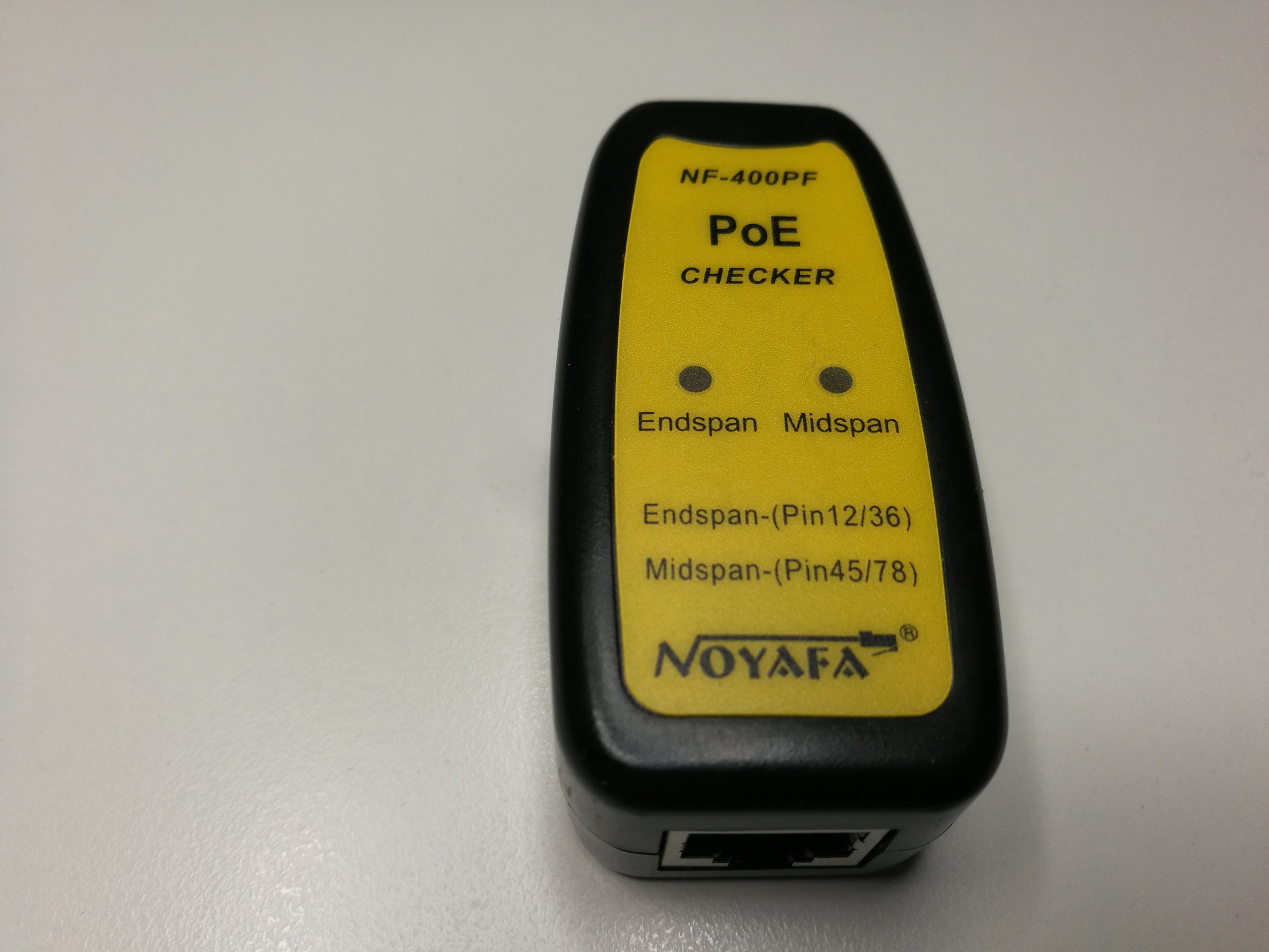
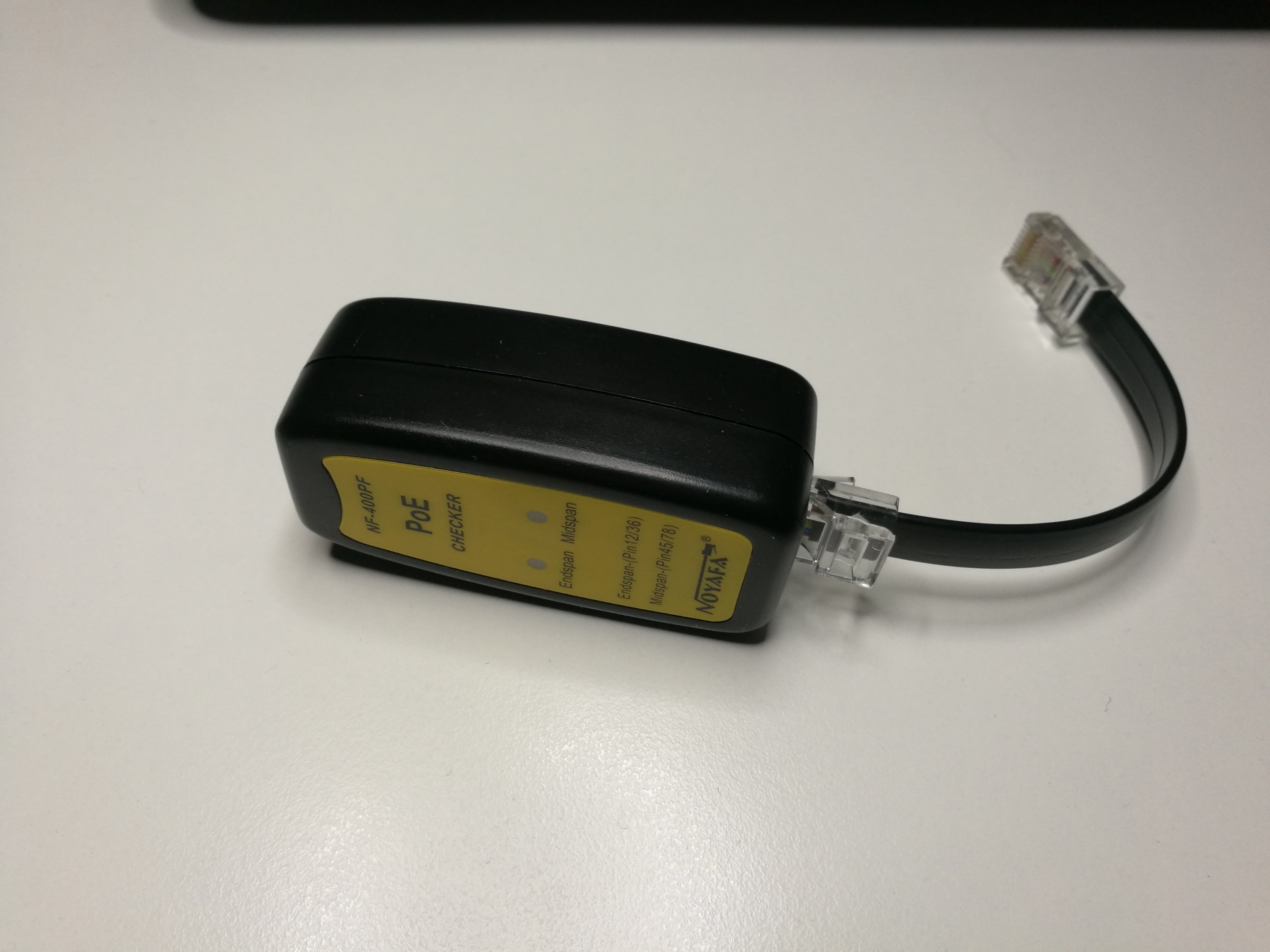
Here is teardown of one cheap power over Ethernet tester from eBay. It worked OK and did what it promised.

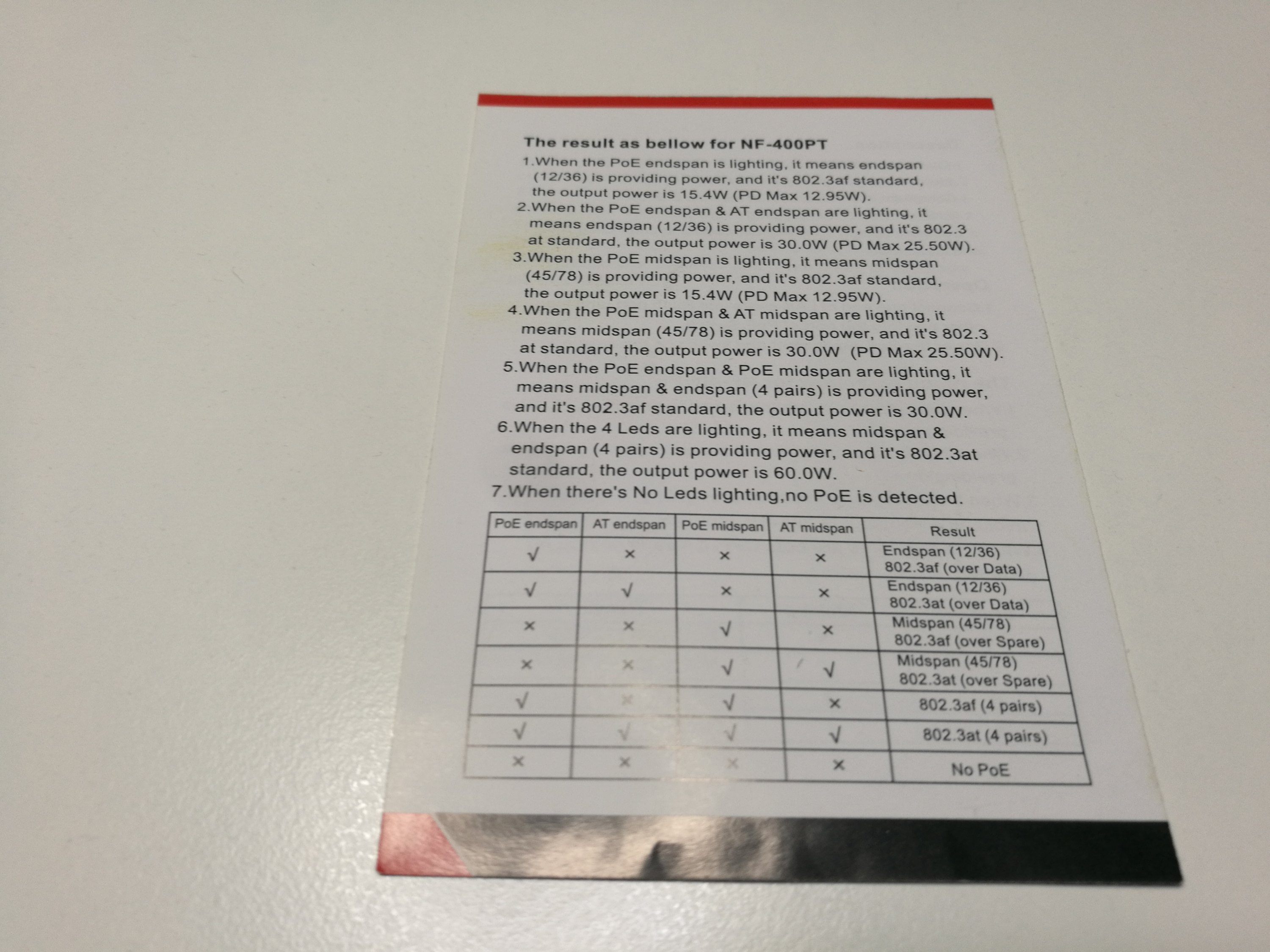
It came with instructions that seem to be for a slightly different model witg more features.
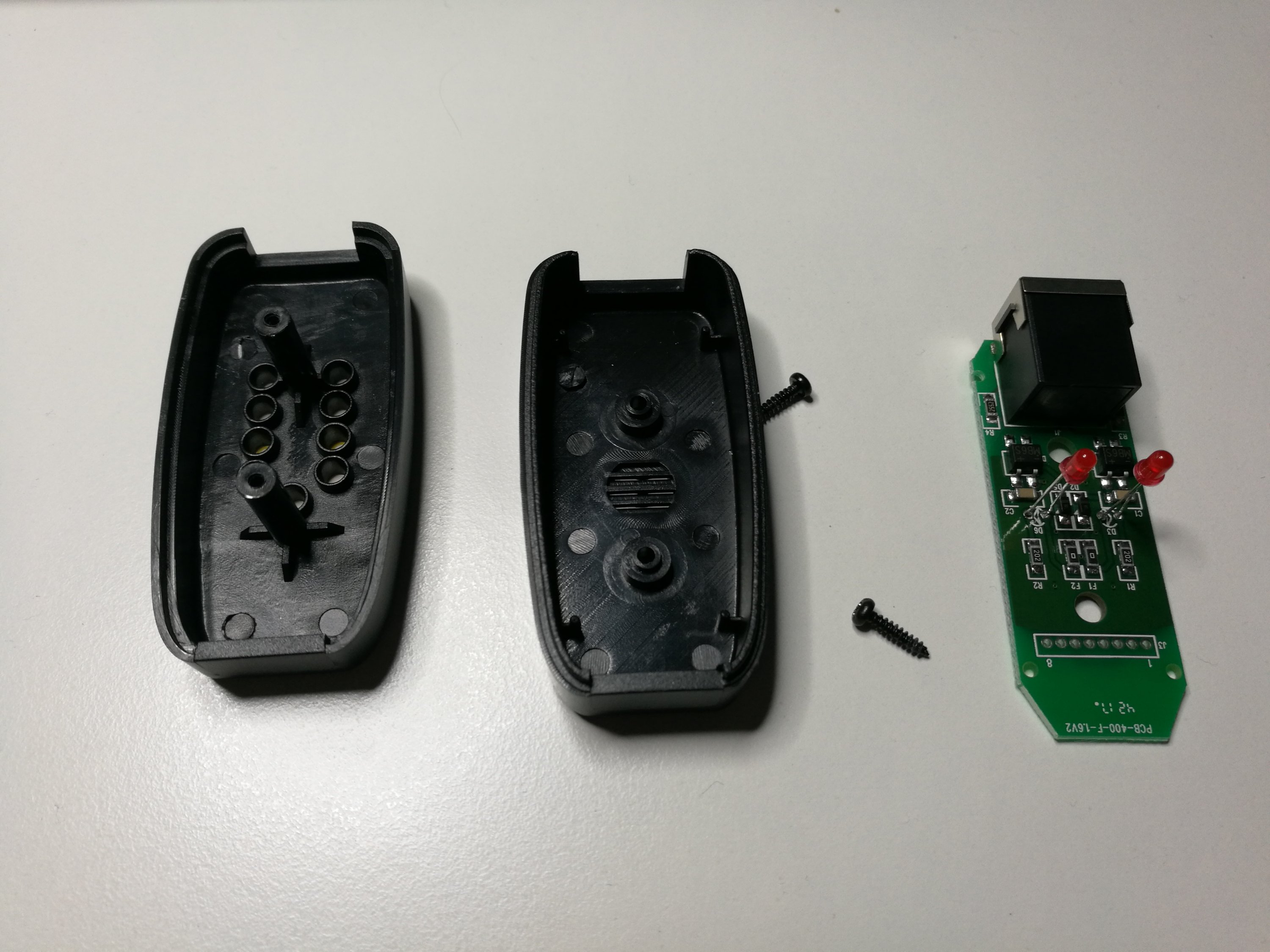
What is inside
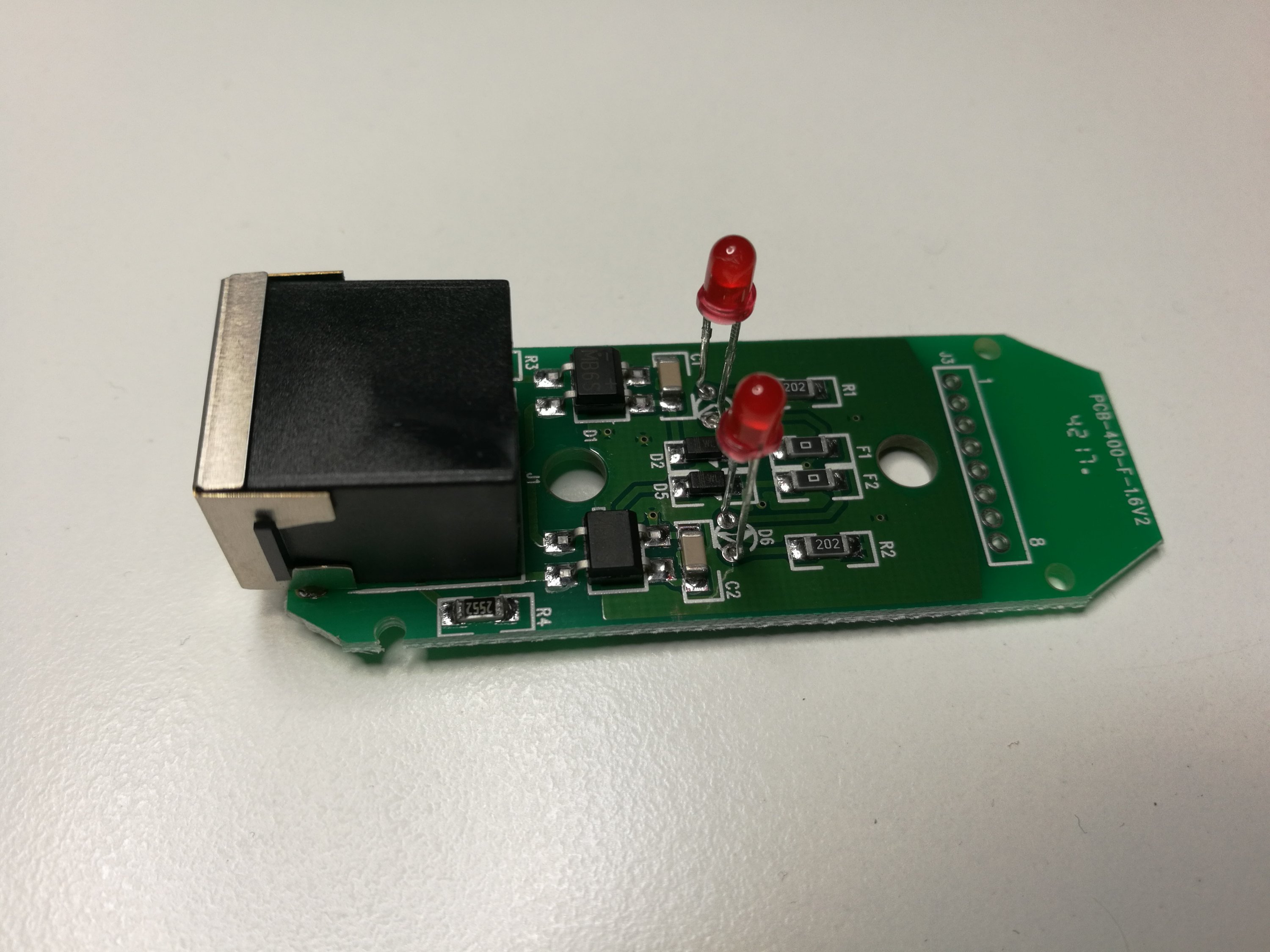
Circuit details. It has two sensing circuits: for end span and middle span power. I have drawn only one of them here.
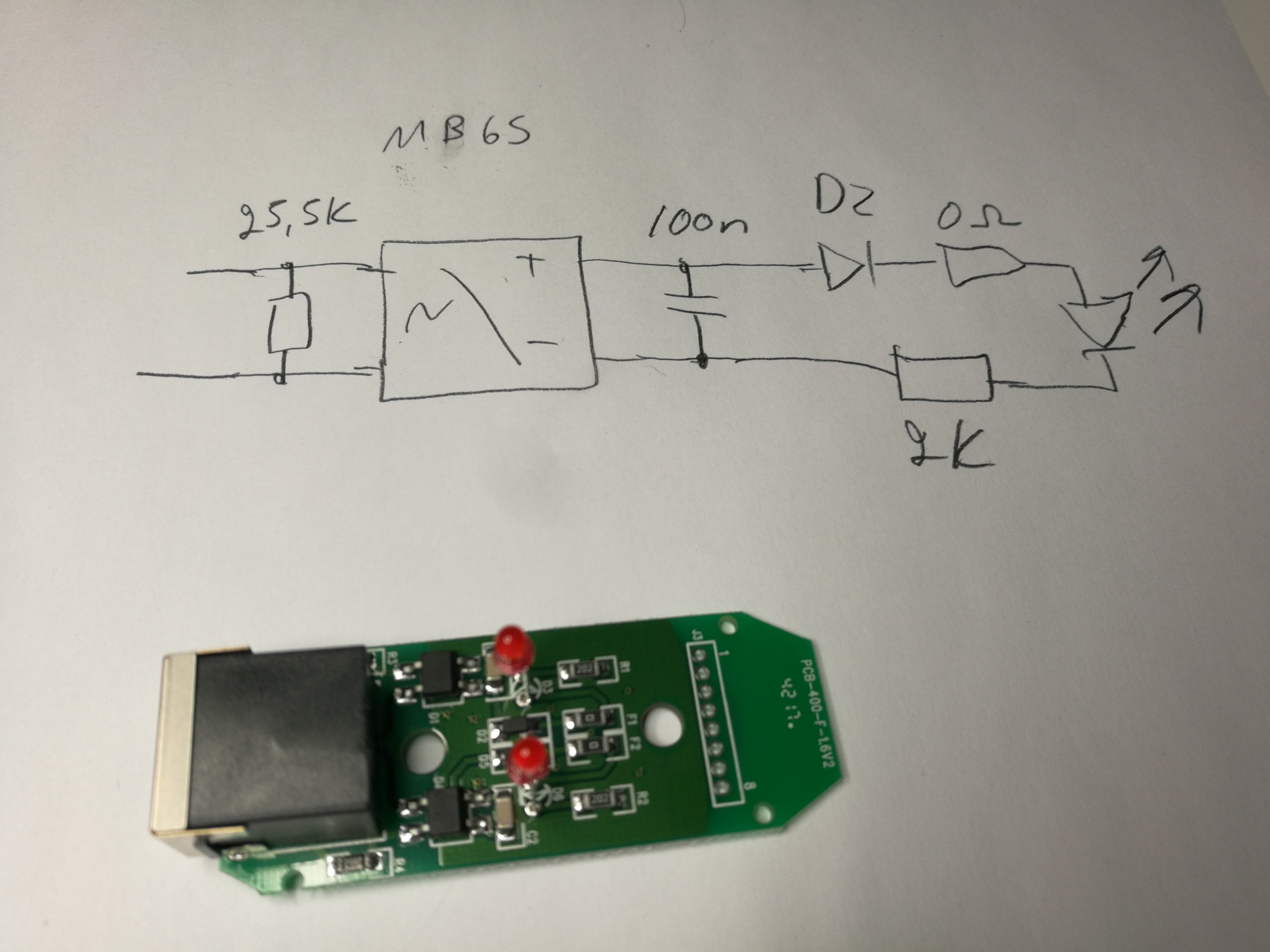
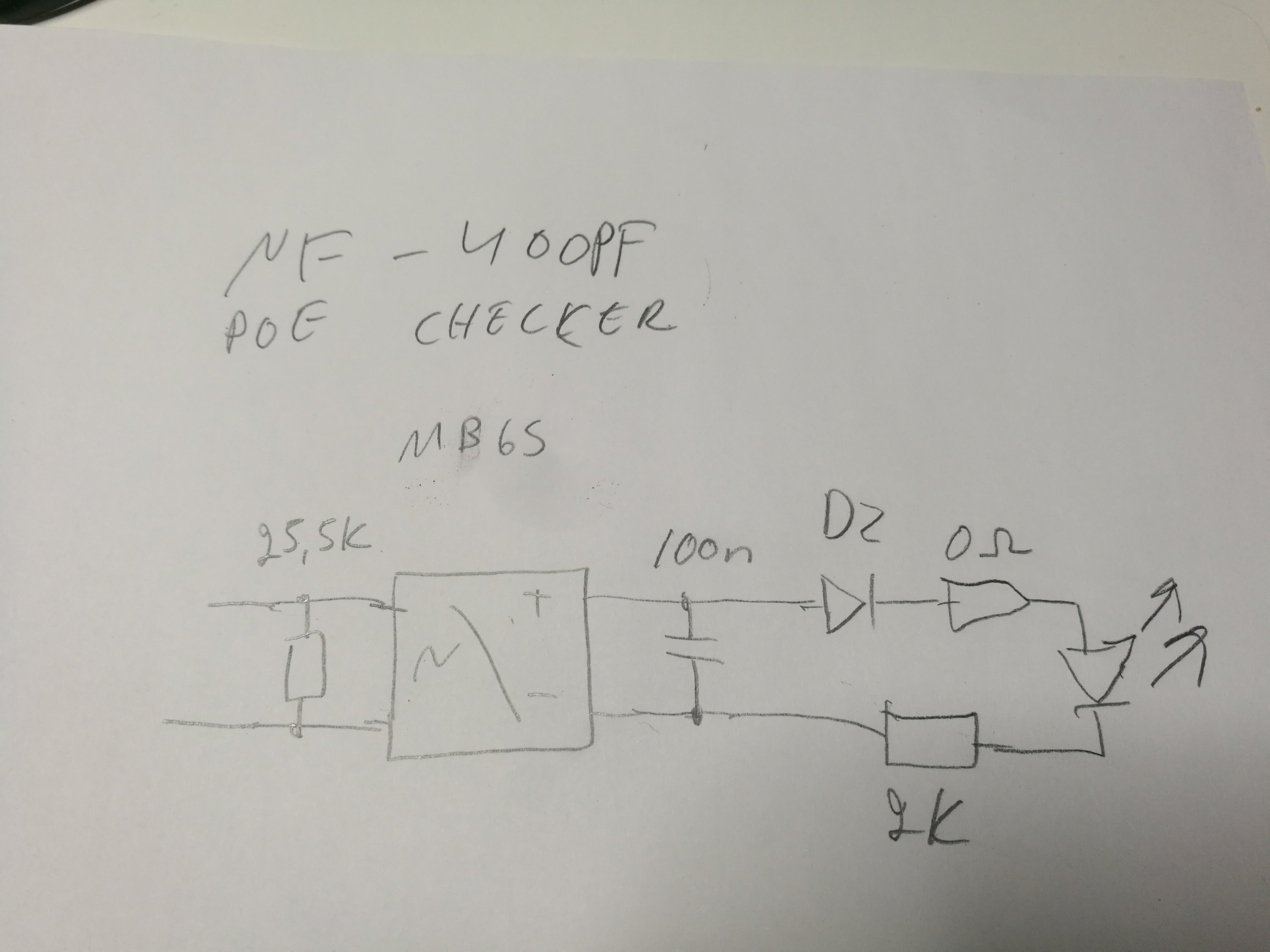
The circuit starts with 25.5 kohm PoE ID resistor that is sensed by power source to detect that there is PoE capable device connected.
The power goes to rectifier and filter capacitor. Next is Dz that I quess is a zener diode (I quess conducts only when voltage is near normal nominal 48V). Next is LED with current limiting resistor.
I did some testing on which voltages the circuit detects. The LEDs start to glow at around 20V DC voltage between PoE pins.
2 Comments
Custom essays says:
The blog post looks to be great. It is an amazing thing if you are looking for PoE tester teardown. The blog post is all about PoE tester teardown and you can get to know all about PoE tester teardown if you go through the post right from the start to the end. The images shown in the pots is of Ethernet tester from eBay.
Brackley says:
Greetings,
Instead of the diode bridge couldn’t one use two LEDs and two zenners in inverse parallell?
I’m thinking of making one but with higher value resistors and no zenners. Hopefully the brightness of the leds should indicate sufficient power and also polarity.