To introduce a kid to electronics I ordered DIY NE555 Electronic Organ Teaching Kit kit from Banggood (cost around 3 Euros). They sell also many other similar kits, but this seemed to be good quality at decent price (around 3 Euro). There was not much information on the product page other than product picture, circuit diagram and this little technical data:
Power supply: DC 3-12V
Board size: 13.5CM* 2.2CM
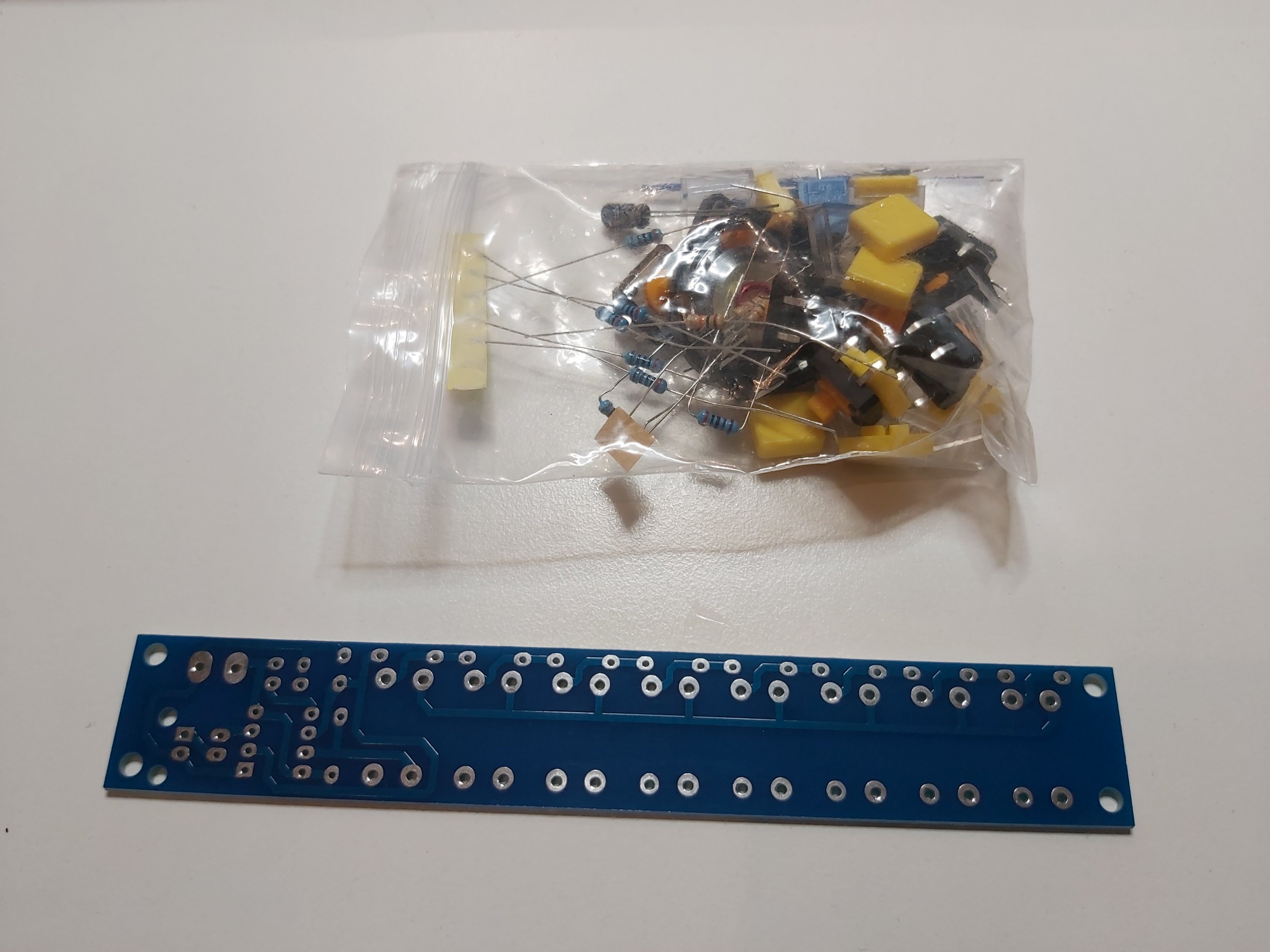
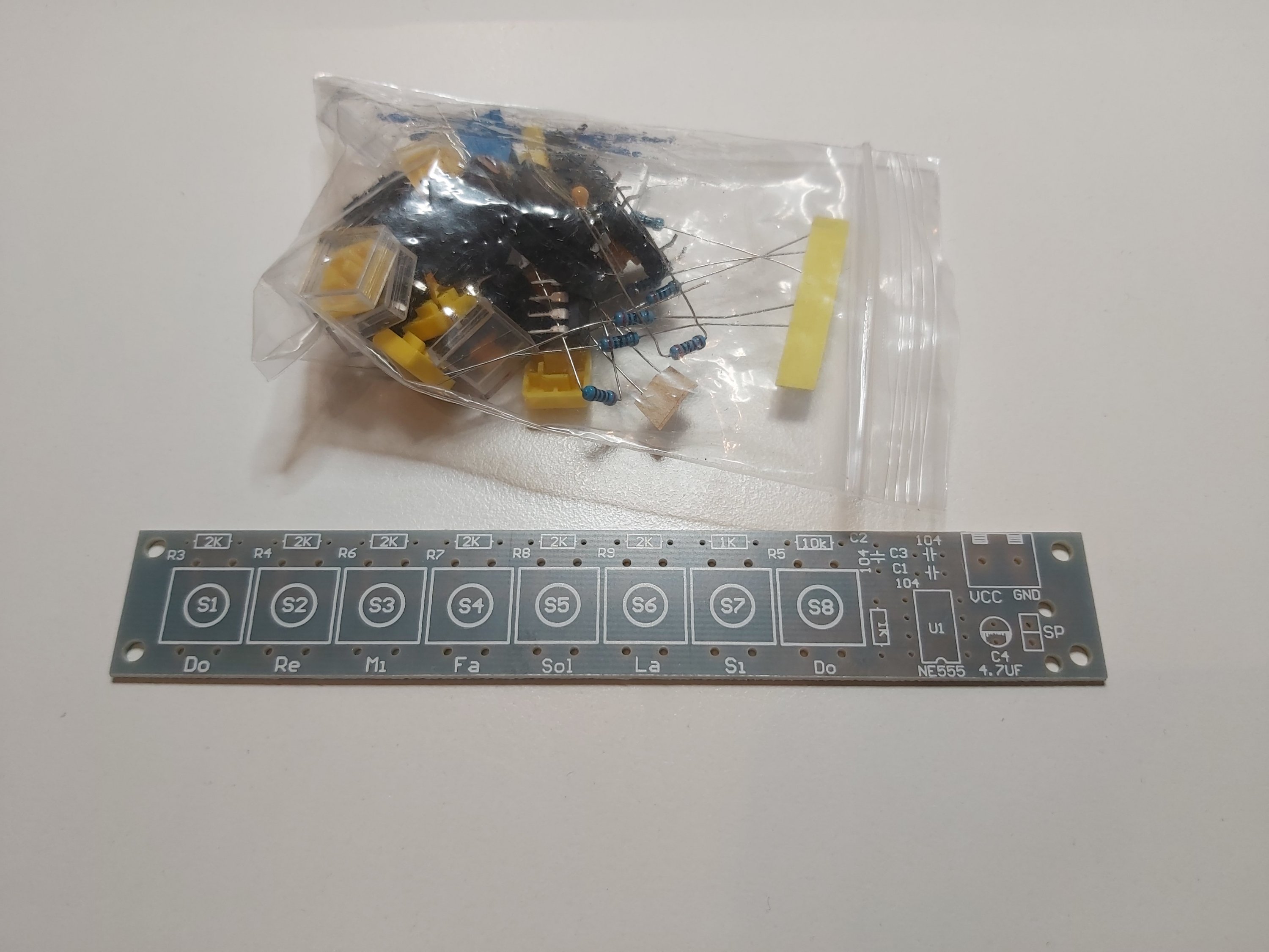
Here are pictures of the circuit board and parts included in the package. There were no building instructions on the package.
Here is picture of the circuit diagram (from a print-out of the product page):
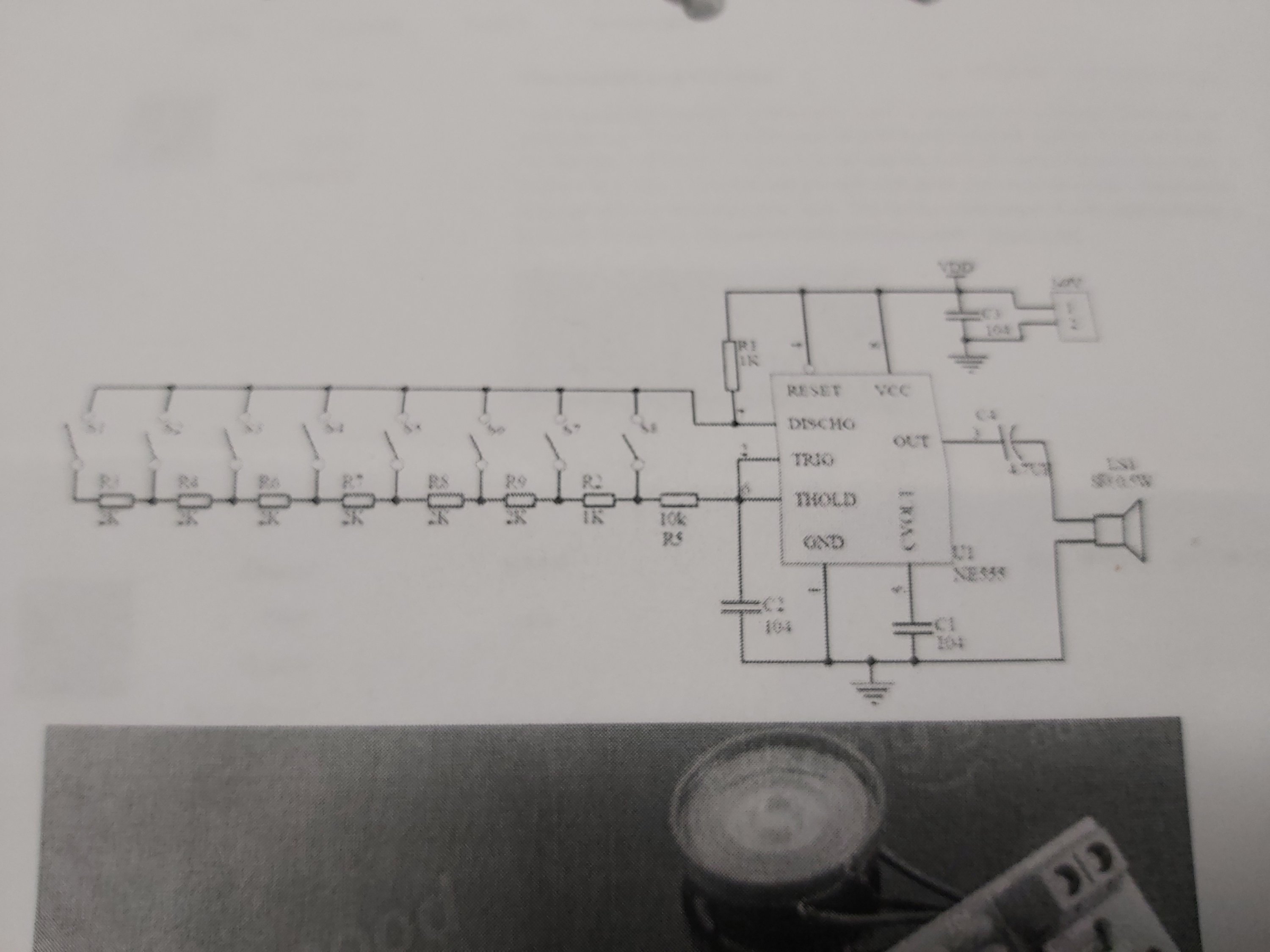
This circuit is a simple electronic toy piano constructed using the popular 555 timer IC. The operation principle is Astable Multivibrator using 555 Timer that generates the needed note frequencies.
This circuit produces a tone according to the button being pressed. Only one button can be pressed at a time, that’s why it is called a monophonic organ. If you press more than one button, you hear the tone of the button that produces highest note. The capacitor C2 (0.1μF) and all the resistors in the above buttons determines the frequency of oscillation of the astable multi-vibrator. Output frequency of NE555 based oscillator can be calculated with equation F = 1.44/((R1 + 2 * Rvariable) * C2). Where R1 and C2 are fixed values, 1KΩ and 0.1μF respectively but the value of Rvariable is determined by the switch which is pressed. The value of Rvariable is between 23 kohms (S1 pressed) and 10 kohms (S8 pressed). When no button is pressed, the Rvariable has infinite resistance and the oscillator is stopped.
Capacitor C1 (0.1μF) is connected to 5th pin of NE555 to avoid high frequency noises and make NE555 work reliably. The 4.7μF capacitor act as a coupling capacitor which will block dc and bypass ac signals to the loudspeaker.
The circuit is specified to operate at 3-9V DC voltage, which is a bit strange voltage range as the NE555 chips recommended voltage range is 4.5-18V. The circuit seemed to work at 3V, but worked better with 9V battery.
Building pictures:
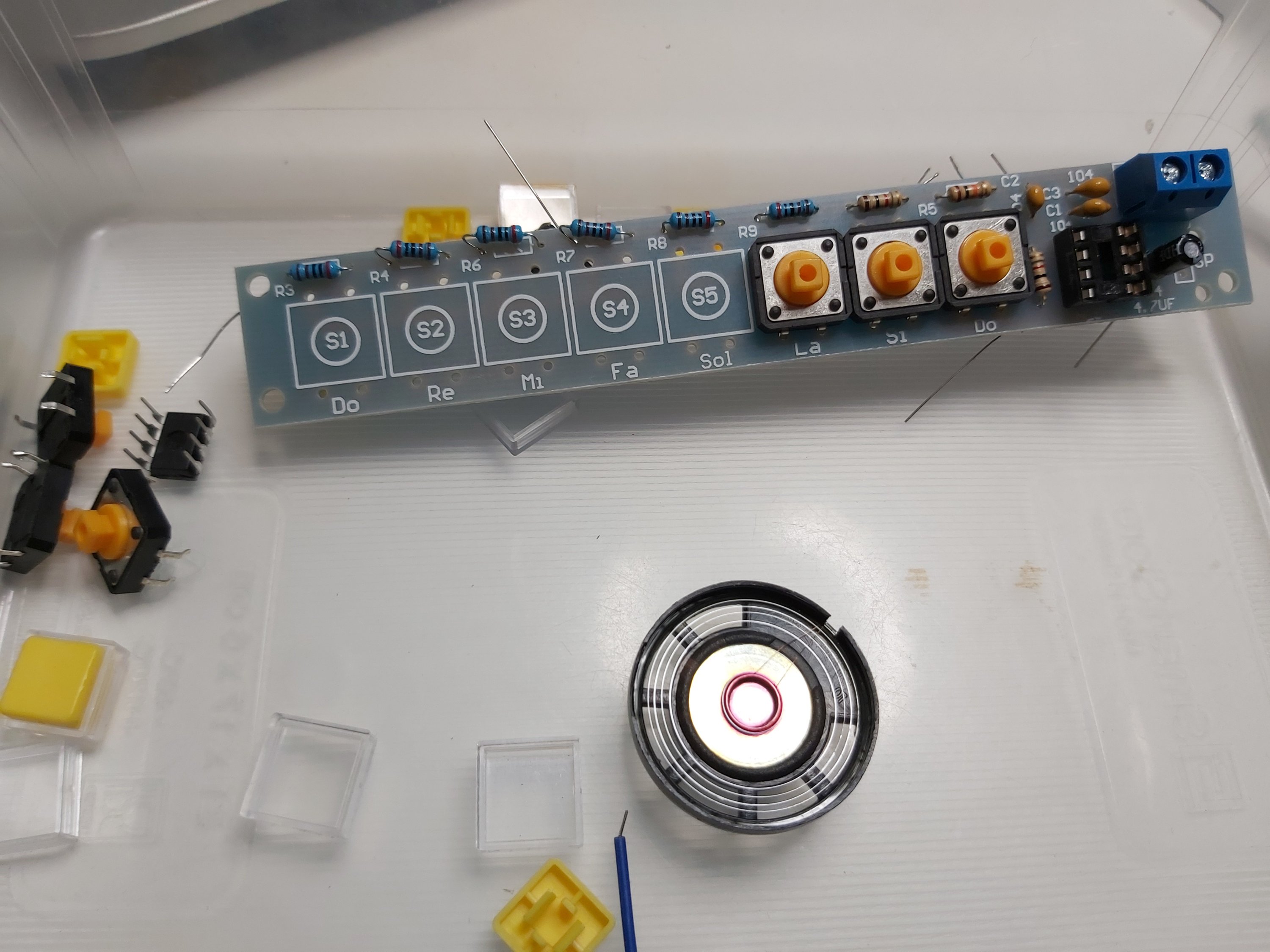
Board built (on the back side of circuit board I had already added two pieces of dual side mounting tape):
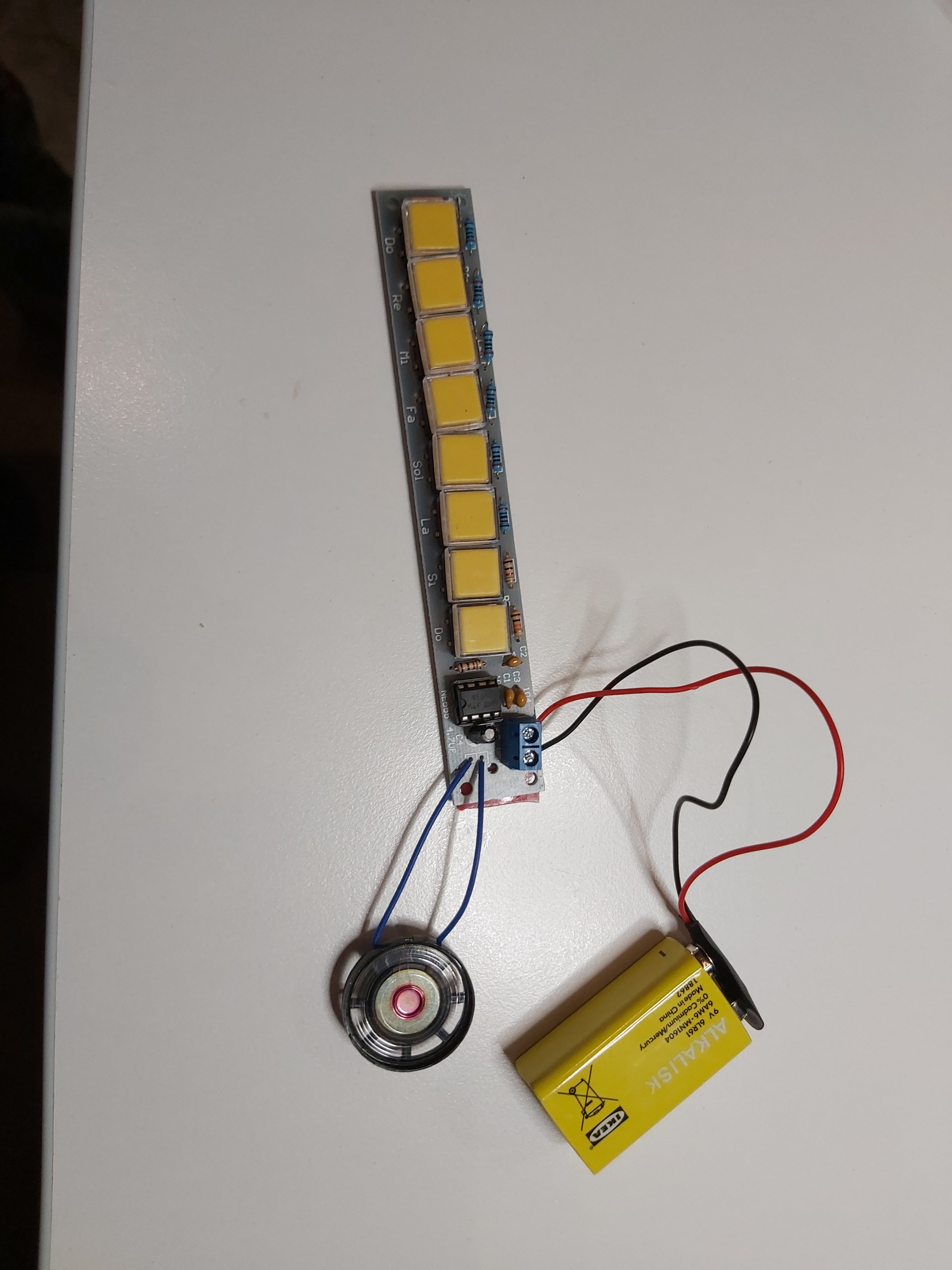
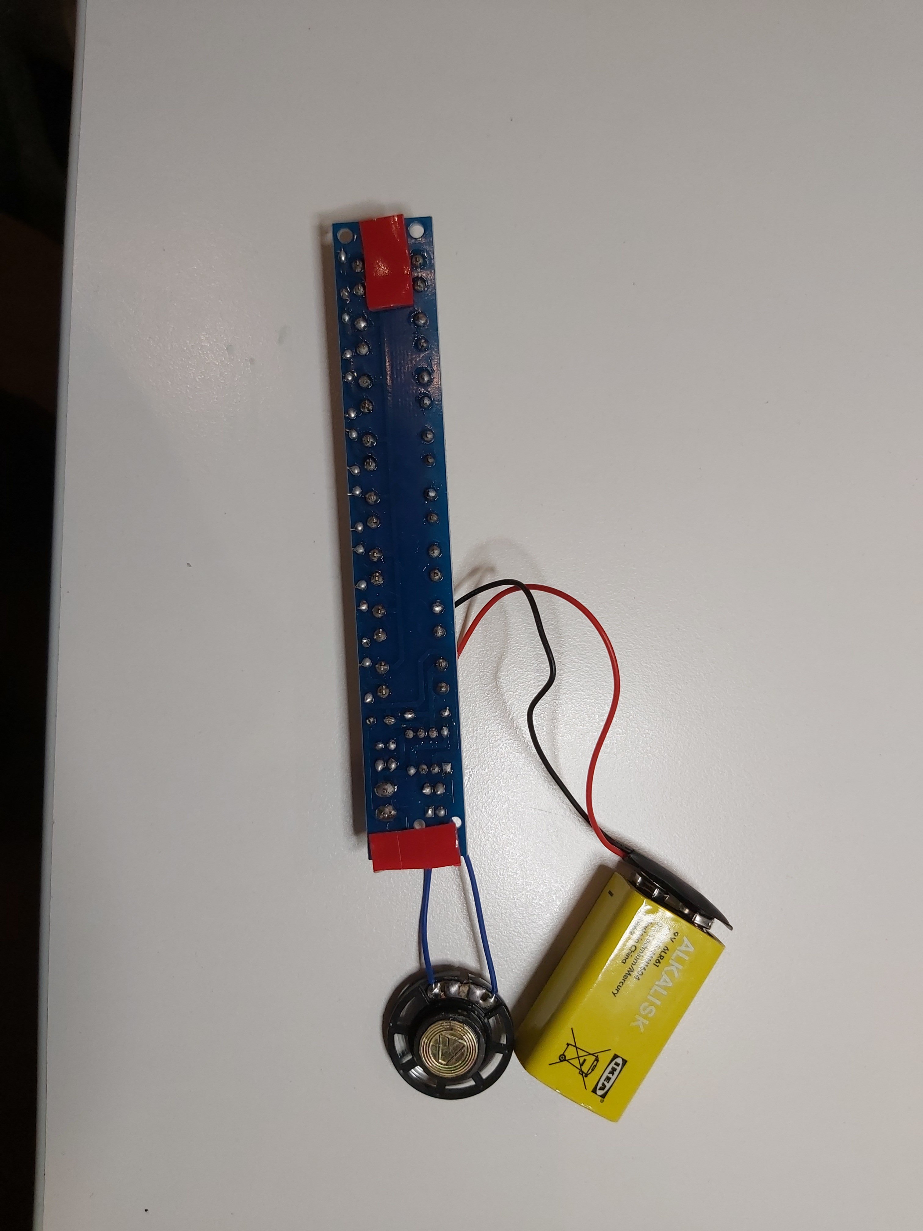
This was a quite good learning kit for the price. It was quick built without any building manual as there were clear markings on the circuit board which goes where. Some of the buttons didn’t quite fit the PCB without bending the legs that were originally somewhat bent here and there. When it was built, it worked well. When I first tested the circuit with 3V, it started to make sounds but at very low volume. When I connected it to 9V battery, it worked very well.
Ready device looks like this when I installed it to some case. I felt the case was needed to keep different parts fixed together and not causing strange noises when fingers touch the back of the circuit board.
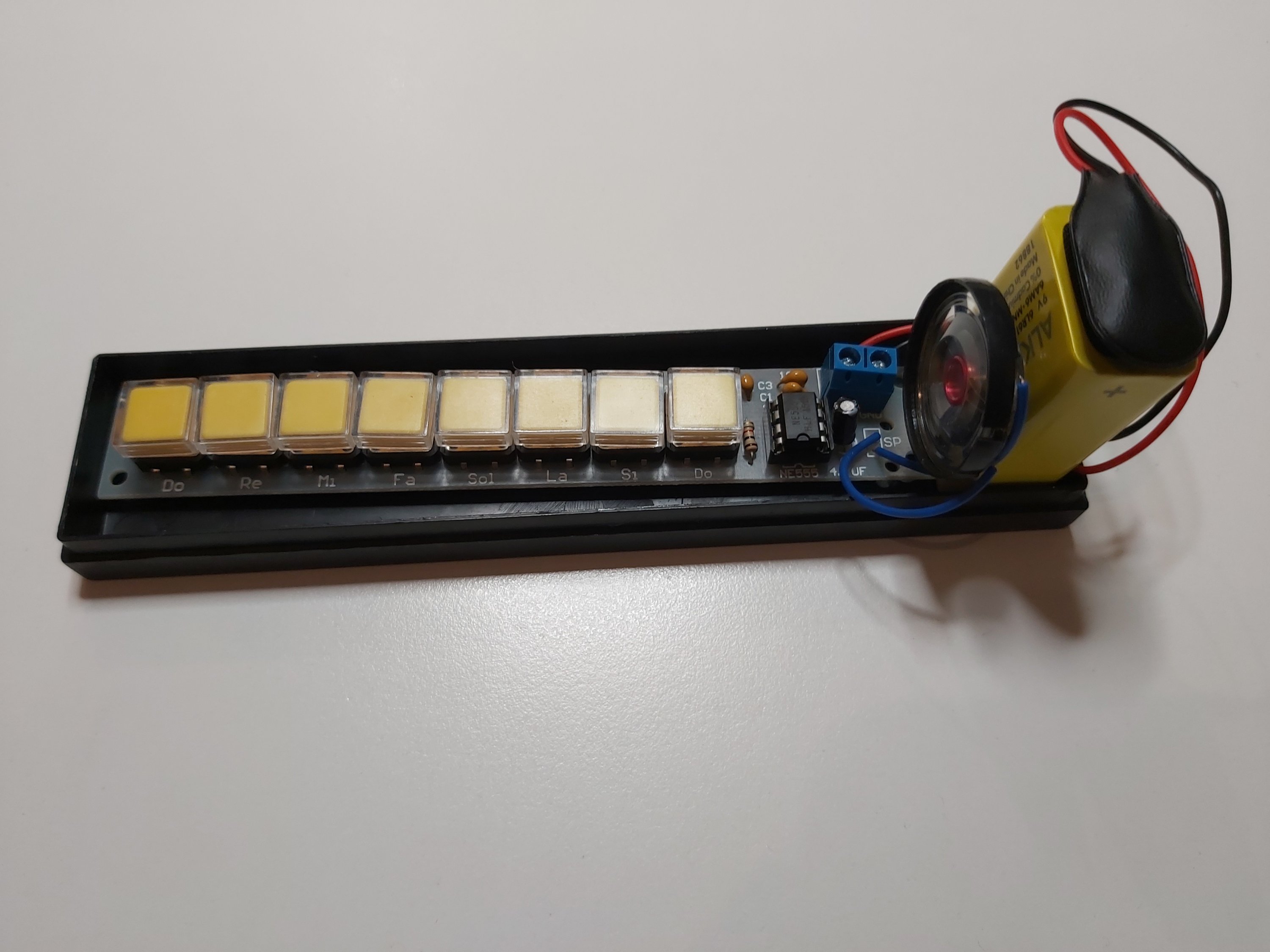
The device sounds pretty close to the similar circuit shown in this video
End verdict: OK quality kit.
4 Comments
Tomi Engdahl says:
Digital Metronome. NE555 Timer
https://m.youtube.com/watch?feature=youtu.be&v=cxs0HYyK6AY
Tomi Engdahl says:
Oskitone’s Polyphonic POLY555 Synth Is Based on 555 Timer ICs
POLY555 Synth is a polyphonic synth, analog, square wave synth with 20 555 timer circuits.
https://www.hackster.io/news/oskitone-s-polyphonic-poly555-synth-is-based-on-555-timer-ics-023be395ea1d
Tomi Engdahl says:
https://www.electroinvention.co.in/mini-piano-using-ic-555
Tomi Engdahl says:
Big Noise From A 555 And A Little Embroidery
https://hackaday.com/2022/09/14/big-noise-from-a-555-and-a-little-embroidery/
The circuit is a riff on a classic 555 timer circuit, which produces a signal that is modulated by applying pressure conductive textile in different ways. The signal is then piped through a system built in a visual coding interface called MaxMSP, which allows [Sam] to get specific on how to control it. The program shifts the pitch and applies filtering, producing a dynamic dial-up tone-like sound as the user interacts.