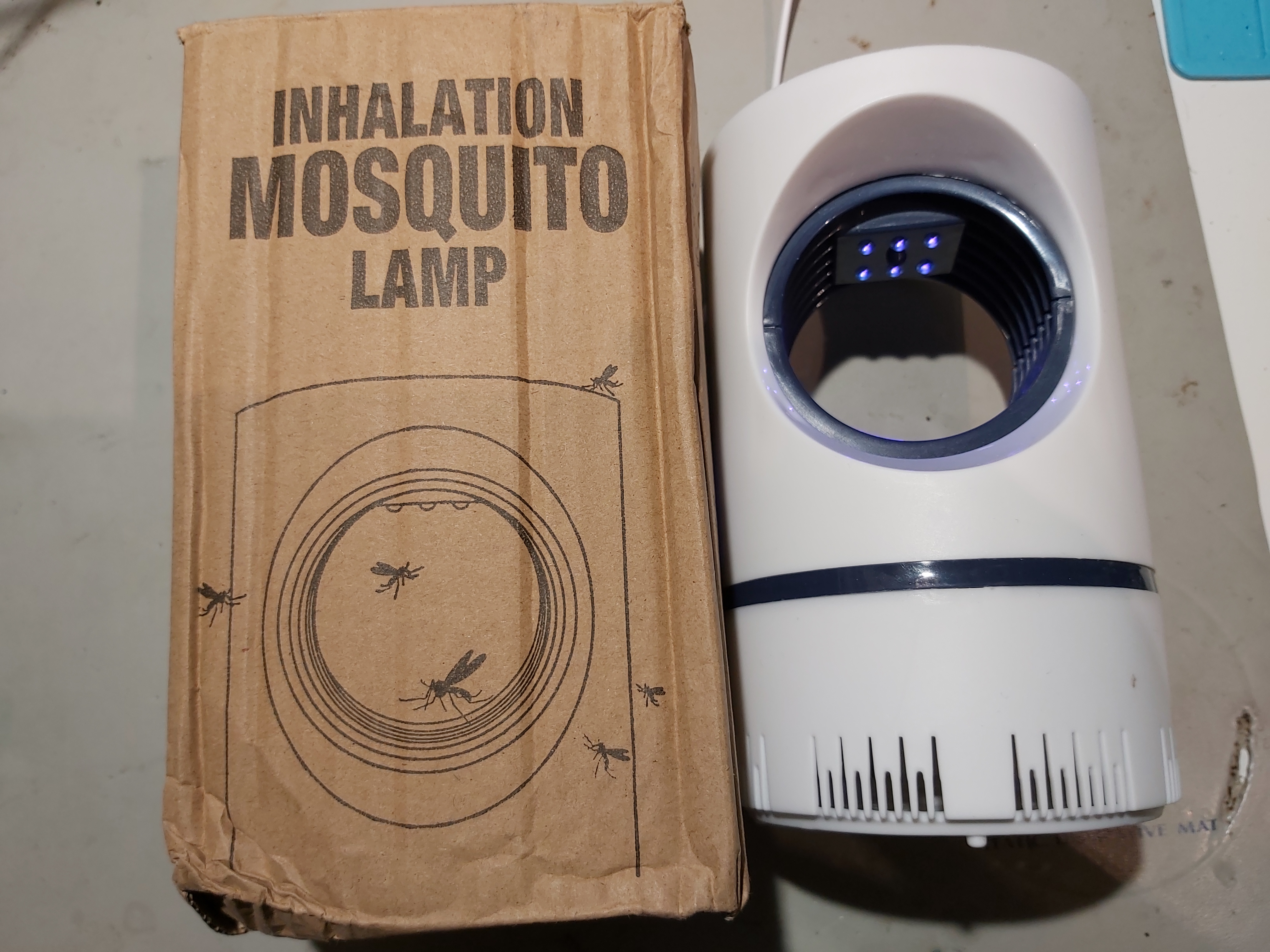
I got few years ago this cheap USB powered mosquito trap. The idea in it is that Blue/UV light gets the mosquitos to go near the device, and then the device sucks them away.
This product was cheap, but was not very effective.
When I tried this device this summer, it did not seem to be even less effective than earlier. It seems that the fan inside seemed to rotate very slowly, so was not effective. I first connected this to an USB power meter, and found out that it consumed much less power (around 130 mA 5V) than the the specifications claimed (5W would be 5V 1A).
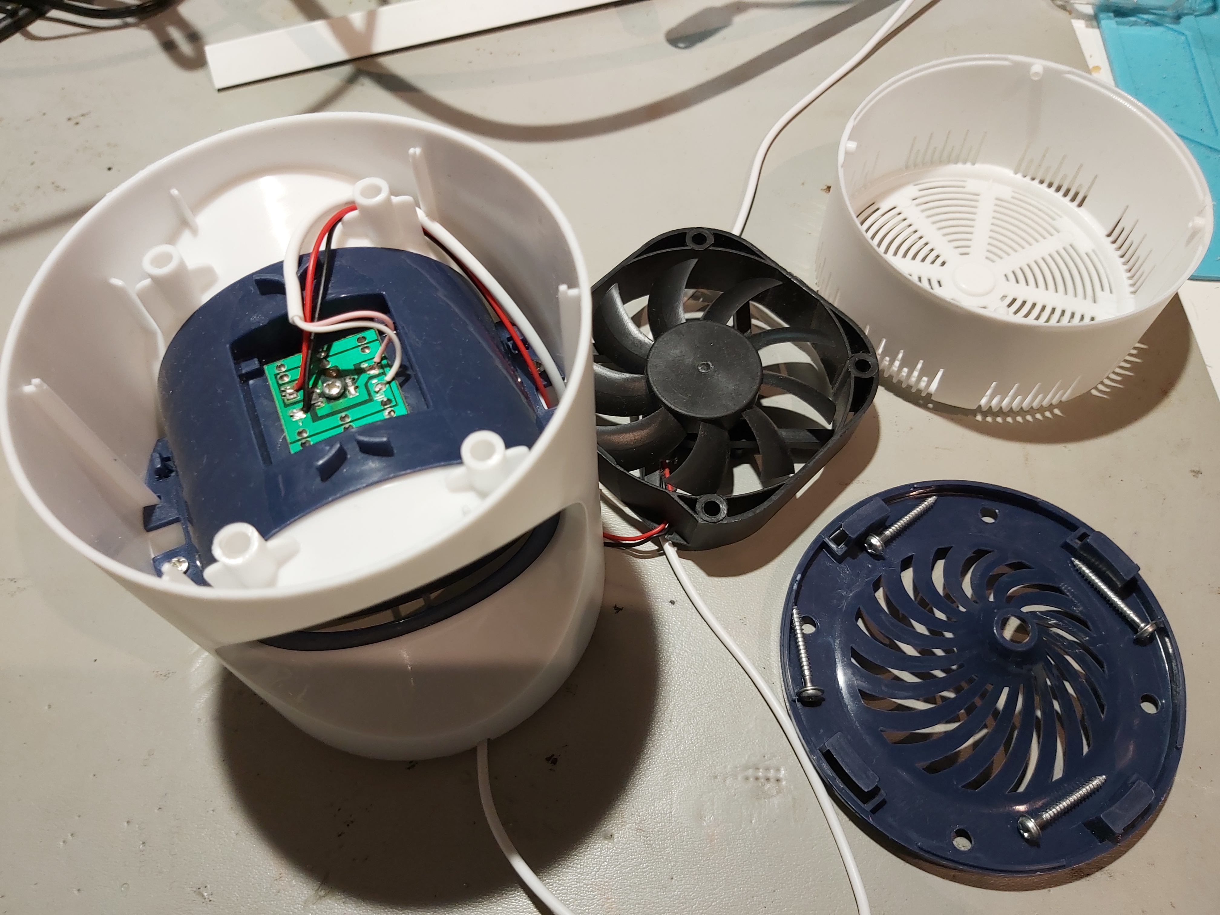
So I opened the device. On the bottom the main component seems to be the fan.
On the upper side there is a circuit board.
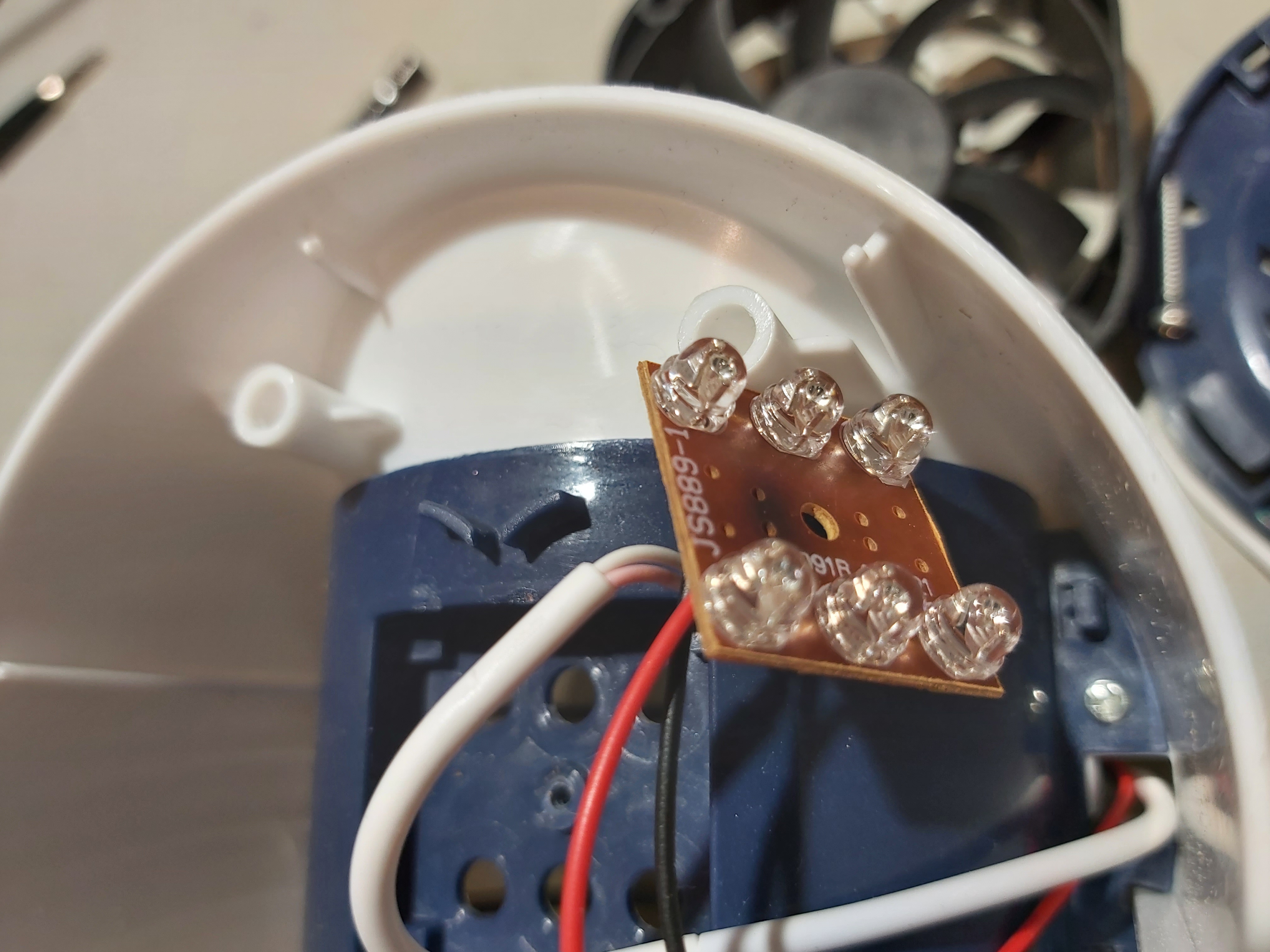
The board has the six LEDs and two resistors. One of the resistors seemed to have been run quite hot.
I measured that the voltage circuit board gives to the FAN is very low, just round 1-2 volts. That is the reason that the fan runs very slowly or barely runs. I found out that the voltage drop happens on that hot running resistor that limits power that goes to the fan.
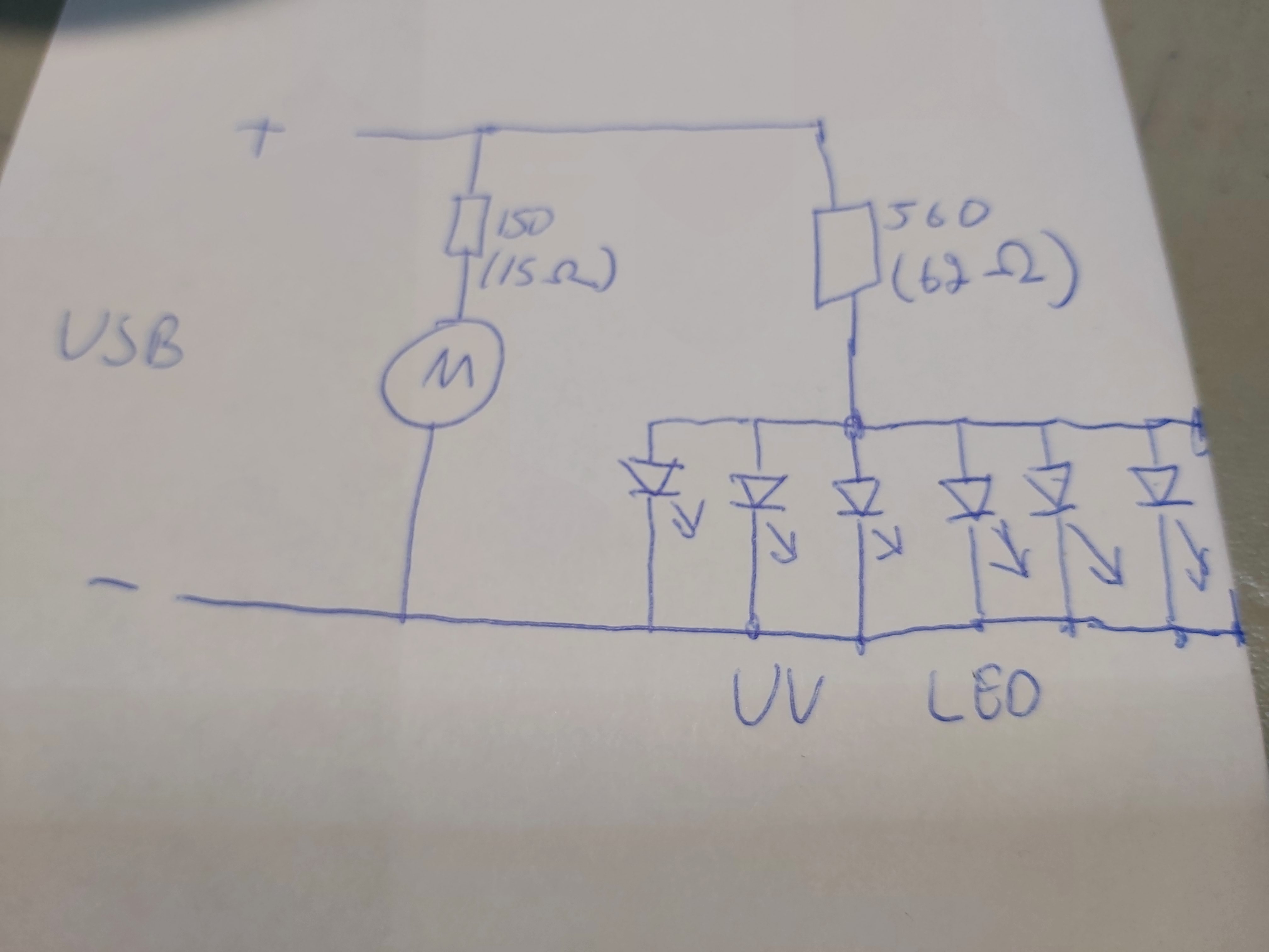
Here is the circuit diagram of the device. I have marked the codes found on the SMD resistors and the resistance value I measured with a multimeter.
It seems that the 15 ohms resistor between the USB +5V and the fan does not make sense here. That would limit the power available to fan to a very low value and get hot at the same time. The fan part seems to be suitable to handle 5V directly. I suspect that the resistor was added to make the fan less noisy, but the value used here is wrong value (too high resistance) for this application. With those component values on the circuit board, this device will never be able to consume power anywhere near 5W and the fan cannot move much air.
The device seems to work more effectively when that 15 ohms resistor is short-circuited. The fan makes some noise, but I can feel some wind produced by it. The device consumes around 3W power after the modification.


0 Comments
Be the first to post a comment.