Year 1999
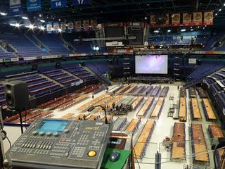
A friend called from a big computer festival Assembly 1999 that was starting. It was one of the biggest this type of event in Europe with thousands of people coming with computers. Some of my friends was running big screen and video streaming for the event.
They had all the stuff rented and set up for the event by the AV contractor. Everything worked flawlessly on the previous day. But on the first day the audio and video system started picking up lots of noise. The audio signal had mains humming in it, and video signals had “humming bars” on them. As more computers get powered up on the hall, the worse the noise becomes. We are not talking about few computers, there was over two thousand computers on the hall.
Same event 2010
I walked in to the even with my tool-set. Solving the audio problems involved sorting out the lines that picked most noise. Most of the audio connections were analogue (both balanced and unbalanced) and most video connections used composite video interface. I walked in to the event with necessary tools. A combination of audio signal isolation transformers and “ground lift” on some balanced audio lines made situation OK.
Video signals were a tougher problem. There were some very long video line runs from the main video mixer to different locations (projectors for big screen, smaller screen etc..). Those long video lines seemed to have lots of noise in them. I measured form 100 mA to 1 ampere mains AC current on coaxial cable shields on the cables with most humming bars! Disconnecting some of those longest lines made the video system to work noise free, but what to do because we can’t live without connections to video projectors.
The main program on the event was starting on the next day, so this problem needs to be solved so that everything works flawlessly or at least “well enough” by tomorrow. I know I would needed some type of video signal isolation devices for those problematic video lines, but our equipment supplier did not have them. It was already quite late night, so it was impossible to try other sources.
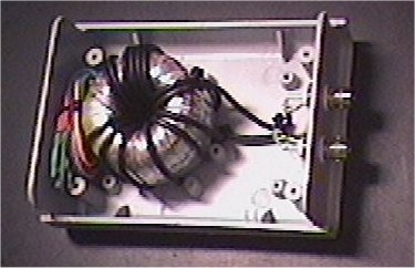
Fortunately I had one prototype of video “humbugging” transformer with me. It was a common mode choke built by winding thin 75 ohm coaxial cable over a suitable toroid transformer core. This device reduces the amount of current flowing on coaxial cable shield and reduces the noise pickup. I built the device based on some old documentation (someone sent me old document from BBC on hum bugging transformers). I tested this DIY “humbugging” transformer on one of the video lines, and it worked very well. The amount of noise on that video line was reduced to point that it could no longer be detected on the big screen.
The problem is that there were also other lines that seemed to need the same kind of treatment. I went to home lab, trying to gather whatever parts I could find to build more such devices. I ended up building three more on the night from the part I could find – I even managed to find nice plastic cases for them. Next morning I came with my brand new “humbugging transformers” to the event. They worked and saved the show next day. What I made looked pretty much like this inside (this is a later made version that uses the same box).
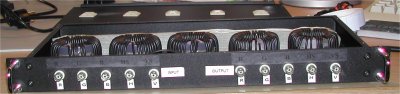
In the end the video equipment provider that rented most of the video gear for the event end up buying my boxes after the event at decent price. I ended later making some more for this company. I ended up making more on then when needed for some video companies. Quite often when I first rented few of them to solve an emergency, they wanted to buy them for themselves.
They have performed very well on many video systems to solve ground loop problems. There are passive hum suppressor transformers that will very effectively remove the hum from the video signal, but do not affect the video signal otherwise. Those special transformers act like a common mode coils, which stop the annoying ground loop currents on the shield of the coaxial cable, but provide a straight path for the signal inside the cable. This type of device is capable of passing the signals from DC to tens of MHz without problems. The hum suppressor transformer both reduces the current flowing on the cable shield and compensated the voltage differences that would otherwise be between cable ends and eventually get to the signal.
You can find more information on my ground loop noise reducing boxes at
https://www.epanorama.net/blog/2009/09/06/build-humbugging-transformer/ and https://www.epanorama.net/blog/2009/09/15/build-video-isolator/ and https://www.epanorama.net/blog/2010/08/12/audio-isolation-transformers/.
I ended doing more audio and video tricks to keep this event running,
36 Comments
Tomi Engdahl says:
Electrical Grounding Explained | Basic Concepts
https://www.youtube.com/watch?v=YO-Dnk6ZKrI
Tomi Engdahl says:
Solving Grounding Issues On Switch Audio
https://hackaday.com/2022/03/27/solving-grounding-issues-on-switch-audio/
Grounding of electrical systems is an often forgotten yet important design consideration. Issues with proper grounding can be complicated, confusing, and downright frustrating to solve. So much so that engineers can spend their entire careers specializing in grounding and bonding. [Bsilvereagle] was running into just this sort of frustrating problem while attempting to send audio from a Nintendo Switch into a PC, and documented some of the ways he attempted to fix a common problem known as a ground loop.
Ground loops occur when there are multiple paths to ground, especially in wires carrying signals. The low impedance path creates oscillations and ringing which is especially problematic for audio. When sending the Switch audio into a computer a loop like this formed.
https://frdmtoplay.com/solving-the-nintendo-switch-ground-loop/
Ground loop isolators are commonly used to remove noise from improperly installed 3rd party car stereos and can easily be found online. Most isolators work by using transformers to transfer the audio signal with a new ground. However, it is not always apparent from the product listing how the isolator actually performs. Since two isolators are needed (one for the mic, one for the stereo) three were purchased and characterized side-by-side.
The three isolators were characterized using a Digilent Analog Discovery 2 as a vector network analyzer with a 2V signal swept from 20Hz-20,000Hz (audible range).
Interestingly, the Zetsage was the only device to reproduce the waveform with a 180° phase offset which inverted at 3kHz! Both the PAC and Kript devices reproduced the waveform with 0° offset after ~100Hz.
With the ground loop resolved it is finally possible to set up the loopback devices allowing the Nintendo Switch speaker output and microphone input to be proxied to other devices.
The total cost to re-implement seems a bit higher than it should! This cost could probably be reduced from hacking together homemade isolation transformers or salvaging TRRS cables.
Tomi Engdahl says:
https://centralindianaaes.files.wordpress.com/2012/09/indy-aes-2012-seminar-w-notes-v1-0.pdf
Tomi Engdahl says:
A ground loop is a type of electrical problem that can occur when there is more than one path for electricity to flow to ground. This can happen when two or more electrical devices, such as computers or other electronic equipment, are connected together and each has its own ground connection. The result is a circulating current that can cause interference, noise, or other problems in the electrical system. Ground loops can be prevented by using a single, common ground connection for all devices, or by using isolating transformers to break the loop.
Tomi Engdahl says:
You must find the source of the hum before you cure it. The are many possible sources. Ripple on the power supply, ground issues both in the amp or in the cabling to other pieces of gear or induction of hum to the output transformer.
Tomi Engdahl says:
Europe:
100Hz buzz – ground loops, and 50Hz hum – poor shielding, cable problems, or close proximity to strong magnetic fields.
USA:
120Hz buzz – ground loops, and 60Hz hum – poor shielding, cable problems, or close proximity to strong magnetic fields.
Tomi Engdahl says:
Understanding & Solving Ground Loops
Ground Control
https://www.soundonsound.com/sound-advice/understanding-solving-ground-loops?utm_source=social&utm_medium=post&utm_campaign=morning_post&fbclid=IwAR0zI-Zz2-DTSIVqNXxqpczqJ6ShNXhG8R6SuOAhHTqMgmSGYkY5xKmlw3k
Tomi Engdahl says:
https://www.soundonsound.com/sound-advice/q-do-balanced-connections-prevent-ground-loops
Tomi Engdahl says:
https://avcsstechworld.com/what-is-a-ground-loop/
Tomi Engdahl says:
https://www.audiosciencereview.com/forum/index.php?threads/ground-loops-measurements-and-solutions.10924/
Tomi Engdahl says:
https://www.analog.com/en/resources/technical-articles/breaking-ground-loops-with-functional-isolation.html
Tomi Engdahl says:
https://circuitcellar.com/resources/ee-tips/find-and-eliminate-ground-loops/
Tomi Engdahl says:
https://hackaday.com/2017/03/09/wtf-are-ground-loops/
Tomi Engdahl says:
https://eliteautogear.com/blogs/news/how-to-fix-a-ground-loop-in-car-audio?srsltid=AfmBOorZk1V3pOmEMVr5tyaMN-2DFk9DRcHbk_S9bi4hsFnjDO3DY1_j
Tomi Engdahl says:
https://www.signalintegrityjournal.com/articles/1202-the-2-port-shunt-thru-measurement-and-the-inherent-ground-loop
Tomi Engdahl says:
https://craiganderton.org/ground-loops-what-they-are-how-to-fix-them/
Tomi Engdahl says:
PCB Ground Loops and How to Prevent Them
https://www.youtube.com/watch?v=3swYweisn5g
Tomi Engdahl says:
https://resources.pcb.cadence.com/blog/2023-what-is-a-ground-loop-and-how-to-minimize-its-harmful-consequences
Tomi Engdahl says:
https://help.campbellsci.com/CR6/Content/shared/Maintain/Troubleshooting/ground-loops.htm
Tomi Engdahl says:
https://www.diese9.com/learn/got-audio-hum-or-buzz-understanding-ground-loops-and-electrical-grounding
Tomi Engdahl says:
https://www.trhf.no/ror/Eliminating_Ground_Loops.html
Tomi Engdahl says:
https://turntableadjustment.com/turntables-deep-dive/how-to-ground-a-turntable/
Tomi Engdahl says:
https://www.valvewizard.co.uk/Grounding.pdf
Tomi Engdahl says:
https://www.cascadetubes.com/2020/01/13/grounding-philosophy/
Tomi Engdahl says:
https://www.jensen-transformers.com/wp-content/uploads/2014/08/generic-seminar.pdf
HOW QUIET IS QUIET?
How much noise and interference is tolerable depends on what the system is and how it’s used. A
monitor system in a recording studio obviously needs much more immunity to ground noise and
interference than a construction site paging system. The dynamic range of a system is the ratio,
generally measured in dB, of its maximum undistorted output signal to its residual output noise or
noise floor — up to 120 dB of dynamic range may be required in high-performance sound systems
in typical homes. [19] In video systems, a 50 dB signal-to-noise ratio is a generally accepted
threshold beyond which no further improvement in images is perceivable, even by expert viewers.
Of course, a predictable amount of “white” noise is inherent in all electronic devices and must be
expected. Excess random noise is generally due to improper gain structure, which will not be discussed here.
Ground noise, usually heard as hum, buzz, clicks or pops in audio signals or seen as hum bars or specks in video signals, is generally much more noticeable and irritating.
MYTHS ABOUT EARTH GROUNDING AND WIRES
As electronics developed, the common return paths of various circuits were also referred to as
“ground,” regardless of whether or not they were eventually connected to earth. In addition, a
single ground circuit most often serves, either intentionally or accidentally, more than one
purpose. Thus, the very meaning of the term ground has become vague, ambiguous, and often
quite fanciful. Some engineers have a strong urge to reduce these unwanted voltage differences
by “shorting them out” with massive conductors — the results are most often disappointing.
Other engineers think that system noise can be improved experimentally by simply finding a
“better” or “quieter” ground. Many indulge in wishful thinking that noise currents can somehow be
skillfully directed to an earth ground, where they will disappear forever!
Here are some common myths about grounding:
Earth grounds are all at zero volts
- n fact, the soil resistance between ground rods is much higher (often tens of ohms) than a wire between them.
Wires have zero impedance — and, therefore, can extend a zero-voltage reference to many
locations in a system, eliminating voltage differences. In fact, wires are quite limited:
- DC resistance
- inductance of a wire
Are EARTH grounds really necessary for low-noise system operation? Think about all the
electronics in an airplane!
Broadly, the purpose of grounding is to electrically interconnect conductive objects, such as
equipment, in order to minimize voltage differences between them. An excellent broad definition is
that a ground is simply a return path for current. We must remember that current always
returns to its source through either an intentional or accidental path
The neutral (white) and line (black) wires are part of the normal load
current circuit shown by the arrows. Note that the neutral (white) and safety ground (green) wires
of each branch circuit are tied or “bonded” to each other and to an earth ground rod at the service
entrance.
PROTECTION FROM DEFECTIVE EQUIPMENT
Any ac line powered device with exposed conductive parts (including signal connectors) can
become a shock or electrocution hazard if it develops certain internal defects. For example,
insulation is used in power transformers, switches, motors and other internal parts to keep the
electricity where it belongs. But, for various reasons, the insulation may fail and effectively connect
“live” power to exposed metal
This low-impedance
connection to neutral allows high fault current to flow, quickly tripping the circuit breaker and
removing power from the circuit. To function properly, the SAFETY GROUND MUST RETURN TO
NEUTRAL. Note that the earth connection had absolutely nothing to do with this process!
If a proper safety ground isn’t available, always use a ground-fault circuit interrupter or GFCI.
Defeating safety grounding is both dangerous and illegal – it also makes you legally liable!
It is current that determines
severity of electric shock. At 1 mA or
less, it’s simply an unpleasant tingle.
But at about 10 mA, involuntary muscle
contractions can result in a “death grip” -
or suffocation if the current flows
through the chest. Currents of 50 to 100
mA through the chest usually induce
ventricular fibrillation that leads to death. Always have a healthy respect for electricity!
An EARTH ground is one actually connected to the earth and is necessary for LIGHTNING
protection. Overhead power lines are frequent targets of lightning. Before modern standards such
as the Code existed, power lines effectively directed lightning strikes into buildings, starting fires
and killing people. Therefore, virtually all modern electric power is distributed over lines that have
one conductor connected to earth ground periodically along its length.
Since soil has resistance just like any other conductor, earth ground connections are not at zero
volts, with respect to each other or any other mystical or “absolute” reference point.
Code allows
the resistance to earth (measured with special techniques) of a residential ground rod to be as
high as 25 S. It is far too high to trip the circuit breaker under fault conditions
THE FACTS OF LIFE ABOUT AC POWER
Most systems consist of at least two devices which operate on utility ac power. Although hum and
other problems are often blamed on improper grounding, in most cases there is actually nothing
“improper” about the system grounding. A properly installed, fully code-compliant ac power
distribution system will develop small, entirely safe voltage differences between the safety
grounds of all outlets. In general, the lowest voltage differences (a few millivolts) will exist between
physically close outlets on the same branch circuit and the highest (up to several volts) will exist
between physically distant outlets on different branch circuits. These normally insignificant
voltages cause problems only when they exist between vulnerable points in a system — which is
more unfortunate than improper.
In all real equipment, there are parasitic capacitances between the power line and the
equipment ground. They are the unavoidable inter-winding capacitances of its power transformer
that are never shown in schematic diagrams. Especially if the equipment contains anything digital,
internal electro-magnetic interference (a.k.a. EMI) filters will further add to the capacitance. These
capacitances allow leakage current to flow between power line and chassis/ground inside each
piece of equipment
In UL-approved ungrounded (i.e., 2-prong ac power plug) devices, this current is limited to
0.75 mA.
Because this equipment is
ungrounded, it’s chassis (or input/output connections) can assume relatively high voltages with
respect to the ground system. Although a voltmeter may indicate well over 50 volts, the current
available is small and will cause only a slight tingle if it flows through a person. However, any
connection between two such devices or such a device and a grounded one will carry this leakage
current. We must accept this fact as reality.
In UL-approved grounded (i.e., 3-prong ac power plug) devices, leakage current is limited to 5 mA.
It flows into the safety ground and accumulates in a branch circuit, generating small voltage drops
in the resistance of the wiring. However, for grounded equipment, the effects of leakage current
are usually insignificant compared to voltage differences between outlet grounds. Substantial
voltages are magnetically induced in premises safety ground wiring by the imperfect cancellation
of magnetic fields that surround the two load-current-carrying conductors.
In any case, a
small but significant ground voltage difference (1 volt is not unusual) will exist between the chassis
or local “ground” of any two pieces of safety-grounded equipment. We must also accept this fact
as reality.
Power-line voltage normally consists of a broad spectrum of
harmonics and noise in addition to the pure 60 Hz sine wave.
Sadly, most audiophile and virtually all consumer audio
devices still use unbalanced interfaces that are inherently extremely susceptible to power-line noise.
An interface may be
unbalanced or balanced,
depending only on the impedances (to ground) of the line’s two conductors. As shown above, in
an unbalanced interface, one conductor is grounded (zero-impedance) and the other has some
higher impedance.
Zo ranges from 100 S to 1 kS and Zi ranges from 10 kS to 100 kS. This transfers
90% to 99.9% of the available signal voltage.
HOW THE NOISE GETS IN
With ungrounded devices, power-line leakage current flows in the grounded signal conductor. [10]
Since this conductor has resistance, a small noise voltage is generated over its length. Because
the interface is a series circuit, this noise voltage is directly added to the signal arriving at the receiver.
Because the impedance of the grounded conductor is “common” to both signal and noise
current paths, this mechanism is called common impedance coupling.
Consider a 25-foot interconnect cable with foil shield and a #26 AWG drain wire. From standard
wire tables (or actual measurement) its shield resistance is found to be 1.0 S. The resistance of
the inner conductor is insignificant and is not discussed here. If the leakage current is 316 :A, the
noise voltage will be 316 :V. Since the !10 dBV reference level for consumer audio is 316 mV,
the noise will be only 20 x log (316 :V ÷ 316 mV) = !60 dB relative to the signal. For most
systems, this is a very poor signal-to-noise ratio. Replacing the cable with Belden #8241F, for
example, would reduce shield resistance to 0.065 S and reduce noise by about 24 dB!
Common-impedance coupling can become very severe in an unbalanced interface between two
grounded devices. Any ground voltage difference developed in the building wiring, which generally
ranges from a few millivolts to a volt, is effectively impressed across the ends of the grounded
signal conductor, typically the cable shield.
FINDING THE PROBLEM INTERFACE
Under fortuitous conditions, systems may be acceptably quiet in spite of poor techniques.
we understand how
grounding systems and interfaces actually work and how noises couple into signals, finding and
fixing problems becomes simple and logical.
Perhaps the most important aspect of troubleshooting is how (or if) you think about the problem.
Without a methodical approach, chasing noise problems can be both frustrating and time-
consuming.
Don’t start by changing things!
Ask questions! Troubleshooting guru Bob Pease suggests these basics: Did it ever work right?
What symptoms tell you it’s not working right? When did it start working badly or stop working?
What other symptoms showed up just before, just after, or at the same time?
Be alert to clues from the equipment itself!
For example, if the noise is unaffected by the setting of a volume control or selector, logic dictates that it must be entering the signal path after
that control. If the noise can be eliminated by turning the volume down or selecting another input,
it must be entering the signal path before that control
Write everything down! Less than perfect memory can waste a lot of time.
Sketch a block diagram of the system! Show all signal interconnecting cables, including digital
and RF, and indicate their approximate length. Mark any balanced inputs or outputs. Generally,
stereo pairs can be indicated with a single line. Note any equipment that’s grounded via its 3-
prong power plug. Note any other ground connections such as cable TV or DSS dishes.
Work through the system backwards! As a general rule, and unless clues suggest another
starting point, always begin at the inputs to the power amplifiers (for audio systems) or the input to
the monitor (for video systems) and sequentially test interfaces backward toward the signal
sources.
Easily constructed test adapters or “dummies” allow the system to test itself and pinpoint
the exact entry point of noise or interference.
Be very
careful not to damage speakers or ears! The surest
way to avoid problems is to turn off the power
amplifier(s) before re-configuring cables for each test
step.
SOLUTIONS
Devices called “ground isolators” solve the fundamental problem with unbalanced interfaces.
Broadly defined, they are differential responding devices with high common-mode rejection. An
isolator is NOT A FILTER that can magically recognize and remove noise when placed anywhere
in the signal path. In order to solve the problem, an isolator must be installed in the signal path
at the point where the noise coupling actually occurs
Transformers make
excellent ground
isolators.
the reduction in ground noise depends critically on the type of transformer used. There
are two basic types of audio transformers. The first type, known as output, puts primary and
secondary windings very close together. The considerable capacitance thus formed allows noise
current to couple between windings, especially at higher audio frequencies. Of course, this current
couples noise into the signal as it flows in the cable shield. The second type, known as input,
places a shield between the windings. Called a Faraday shield (not a magnetic shield), it
effectively eliminates the capacitive coupling between windings, vastly improving noise rejection.
There are a remarkable number of “black
boxes” on the market intended to solve
“ground loop” problems. This includes
quite a number of transformer-based
boxes. With very rare exception, those
boxes contain output transformers.
While boxes containing input transformers offer some 30 dB
better noise rejection, their high-frequency response is degraded by excessive cable capacitance
at their outputs. Results are always better, but they must be installed near the equipment input
using no more than 2 or 3 feet of cable
Check performance data for isolators carefully. Many have
scanty, vague, or non-existent specs — and many use cheap,
telephone-grade transformers!
When a system contains two or more pieces of grounded equipment, whether via power-cords or
other ground connections, a “ground loop” may be formed.
A safe way to break the ground loop is to install a ground isolator
somewhere in the audio signal
Another safe solution is to break the loop by installing a ground isolator in the CATV signal path
Since most consumer equipment uses 2-prong ac plugs (ungrounded), installing an isolator may
leave some devices “floating.” This can allow the voltage between the input and output ports of an
isolator to approach 120 volts ac.
While not dangerous, this situation puts an extreme and unnecessary rejection burden on the
isolator!
Strong ac electric fields (often inaccurately
called electrostatic fields) surround any
conductor operating at a high ac voltage —
neon signs and ac power cords, for example.
The field strength falls off rapidly with
distance. Enclosing signal conductors in a
shield can prevent noise coupling due to
these electric fields
Electric fields usually cause noise problem only when the driving
source has very high impedance, as with some vacuum-tube audio consumer gear. Noise is
generally not an airborne contaminant “picked up” by cables with inadequate shielding.
Unbalanced cables are susceptible to ac magnetic fields. Regardless of cable construction,
unbalanced interfaces are susceptible to noise induced by nearby ac magnetic field sources.
Unlike balanced interfaces, the noise cannot be nullified by the receiving input
Audio cables are NOT transmission lines.
NO OTHER PRODUCT IS AS SHROUDED IN HYPE AND MYSTERY AS THE AUDIO CABLE!
Expensive and exotic cables, even if double or triple shielded, made of 100% pure un-
obtainium, and hand-made by a team of virgins, will have NO significant effect on hum and
buzz problems!
In engineering terms, a high-performance cable for unbalanced audio should have low
capacitance and very low shield resistance. A good example of such a cable is Belden #8241F. Its
17 pF per foot capacitance allows driving a 200 foot run from a typical 1 kS consumer output while
maintaining a !3 dB bandwidth of 50 kHz. Its low 2.6 mS per foot shield resistance is equivalent
to #14 gauge wire, which can significantly reduce common-impedance coupling. It’s also quite
flexible and available in many colors
A CHECKLIST
Keep cables as short as possible. Longer cables increase the common-impedance
coupling. Coiling excess cable length invites magnetic pickup.
Use cables with heavy gauge shields. This is especially important when cables must be long.
The only property of cable that has any significant effect on audio noise coupling is shield
resistance.
Bundle signal cables. All signal cables between any two boxes should be bundled. For example,
if the L and R cables of a stereo pair are separated, nearby ac magnetic fields will induce a
current in the loop area inside the two shields — coupling hum into both signals. Bundling all ac
power cords separately helps to average their magnetic and electrostatic fields, which reduces
their net radiation. Of course, keep signal bundles and power bundles as far apart as possible.
Maintain good connections. Connectors left undisturbed for long periods can oxidize and
develop high (and often distortion-producing non-linear) contact resistance. Hum or other noise
that changes when the connector is wiggled indicates a poor contact. Use a good commercial
contact fluid and/or gold plated connectors to help prevent such problems.
DO NOT ADD unnecessary grounds. Additional grounding of equipment tends to increase
system ground noise current rather than reducing it. Of course, NEVER disconnect a safety
ground or lightning protection ground to solve a problem.
Use ground isolators at problem interfaces. Isolators are a “silver bullet” solution for common-
impedance coupling, which is the major weakness of unbalanced interfaces.
BALANCED AUDIO INTERFACES
An interface may be unbalanced or balanced, depending only on the impedances (to ground) of
the line’s conductors. In balanced interfaces, both conductors have equal (and non-zero)
impedances. A balanced interface requires that driver, line, and receiver all maintain balanced
impedances to ground. Balanced interfaces are extremely potent in preventing all kinds of noise
coupling. In fact, it’s so powerful that many systems, such as telephone systems, use it instead of
shielding as the main noise reduction technique!
The true nature of balanced interfaces is widely misunderstood.
Quoting a part of the informative annex of IEC Standard 60268-3: “Therefore,
only the common-mode impedance balance of the driver, line, and receiver play a role in noise or
interference rejection. This noise or interference rejection property is independent of the presence
of a desired differential signal. Therefore, it can make no difference whether the desired signal
exists entirely on one line, as a greater voltage on one line than the other, or as equal voltages on
both of them. Symmetry of the desired signal has advantages, but they concern headroom and
crosstalk, not noise or interference rejection.” An accurate definition is “A balanced circuit is a two-
conductor circuit in which both conductors and all circuits connected to them have the same
impedance with respect to ground and to all other conductors. The purpose of balancing is to
make the noise pickup equal in both conductors, in which case it will be a common-mode signal
which can be made to cancel out in the load.”
Theoretically, it can
reject any interference,
whether due to ground
voltage differences,
magnetic fields, or
electric fields, as long as
it produces identical
voltages each of the
signal lines and the
resulting peak voltages
don’t exceed receiver
capability. When both devices are grounded to the safety ground system, the ground voltage
difference between them becomes the “ground noise” shown. When one or both devices is
ungrounded, the ground voltage difference can become very large. Traditionally, balanced audio
interconnects use shielded cable with each end of the shield connected to respective device
ground. This connection serves to minimize the ground voltage difference between the devices.
However, if such a connection is absent, other measures may be required to limit the ground
voltage difference. The voltage that appears identically on both inputs, since it is common to both
inputs, is called the common-mode voltage.
A balanced receiver uses a differential device, either a
specialized amplifier or a transformer, which inherently
responds only to the voltage difference between its
inputs. An ideal receiver would have no response to
common-mode voltages. But with real devices, the
response is not zero. The ratio of the device’s differential
gain to its common-mode gain is called its common-
mode rejection ratio, or CMRR. It’s usually expressed
in dB, where higher numbers mean better rejection.
The
nulling of the common-mode voltage is critically
dependent on the ratio matching of these pairs of
driver/receiver common-mode impedances. The nulling is relatively unaffected by impedance
across the lines — only the common-mode impedances matter!
we can minimize the CMRR degradation in a balanced interface
caused by normal component tolerances by making common-mode impedances very low at
one end of the line and very high at the other.
Noise rejection in a real-world balanced interface is often far less than that touted for the
input. That’s because the performance of balanced inputs have traditionally been measured in
ways that ignore the effects of driver and cable impedances.
It’s
very important to understand that noise rejection in a balanced interface isn’t just a function of
the receiver — actual performance in a real system depends on how the driver, cable, and
receiver interact.
PIN 1 PROBLEMS AND THE HUMMER
Dubbed he “pin 1 problem” (pin 1 is shield in XLR connectors) by Neil Muncy, common-
impedance coupling has been inadvertently designed into a surprising number of products with
balanced interfaces. As Neil says, “Balancing is thus acquiring a tarnished reputation, which it
does not deserve. This is indeed a curious situation. Balanced line-level interconnections are
supposed to ensure noise-free system performance, but often they do not.” [16]
The pin 1 problem effectively turns the shield connection into a very low-impedance signal
input. Shield current, consisting mainly of power-line noise, is allowed to flow in internal wiring or
circuit board traces shared by amplifier circuitry. The tiny voltage drops created are amplified and
appear at the device output. When this problem exists in systems, it can interact with other noise
coupling mechanisms to make noise problems seem nonsensical and unpredictable. The problem
afflicts equipment with unbalanced interfaces, too.
Easily constructed test adapters or “dummies” allow the system to test itself and pinpoint the exact
entry point of noise or interference.
SOLUTIONS
The most common problems with balanced interfaces are
due to poor CMRR in the equipment input and “pin 1
problems.” The isolator shown here uses input
transformers to vastly improve CMRR and RF interference
rejection.
The middle
plot shows the effect of using an ordinary output transformer isolator. While 60 Hz hum is reduced
by some 20 dB, the reduction is near zero at 3 kHz. However, a high-performance isolator using
an input transformer reduces 60 Hz hum by almost 60 dB and reduces 3 kHz (buzz artifacts) by
over 20 dB.
beware of products that are not well-specified. They can sometimes solve
noise problems, but at the expense of sound quality.
ABOUT CABLES AND SHIELD CONNECTIONS
As with unbalanced cables, electric fields can capacitively couple noise into signal conductors. In
a balanced interface, equal voltages would theoretically be induced on the two balanced lines.
Since that makes it a common-mode voltage, it is theoretically rejected by the receiver. In
practice, the rejection is limited by the matching of both the capacitive coupling and the line
impedances. The matching of capacitive coupling can be improved by twisting the balanced pair,
averaging their physical positions (and capacitances) relative to the field source. However, a
grounded shield solves the entire problem by simply diverting the noise currents to ground. Here
again, braided shields with 85% to 95% coverage are usually adequate.
Shield ground connections can affect CMRR.
Cable capacitances between each signal
conductor and shield are mismatched by 4%
to 6% in typical cable. If the shield is
grounded at the receiver end, these
capacitances and driver common-mode
output impedances, themselves often
mismatched by 5% or more, form a pair of
low-pass filters for common-mode noise. The
mis-tracking of these filters converts a portion
of common-mode noise to differential signal.
If the shield is simply connected only at the driver,
this conversion mechanism is completely
eliminated because all filter elements are at
the same (driver ground) potential!
Therefore, for shielded balanced audio cables, the shield should
ALWAYS be grounded at the driver — whether or not the receiving end is grounded.
However, this conflicts with “mesh” grounding methods preferred at RF frequencies. To guard
against RF interference, where typical system cables become a fraction of a wavelength,
additional grounding is desirable. Therefore, the most widespread industry practice is to ground
the shield at both ends, which compromises CMRR to some degree. But a high-frequency
treatment can be superposed on the low-frequency treatment to get both highest possible CMRR
and improved RF immunity. This approach, called hybrid grounding, couples the receive end of
the shield to ground through a capacitor. The capacitor is effectively a short circuit at RF
frequencies but an open circuit at audio frequencies.
Strong ac magnetic fields surround any conductor operating at a high ac current — building
wiring, power transformers, motors, and CRT displays, for example. The field strength generally
falls off rapidly with distance from the source.’
In a perfect balanced interface,
equal voltages would be induced in the signal pair, making it a common-mode voltage which
would be completely rejected by the receiver. In practice, the rejection is limited by the degree of
matching in both the magnetic coupling and the line impedances. The matching of magnetic
coupling can be improved by twisting the balanced pair, averaging their physical distance to the
field source. Be sure all balanced line pairs are twisted. Twisting makes shielded or unshielded
balanced pair lines nearly immune to magnetic fields and makes unshielded balanced lines nearly
immune to electric fields.
In magnetically hostile
environments, consider “star-quad” microphone cable — it improves immunity to magnetic fields
by about 40 dB compared to standard shielded twisted pair cable.
Effective magnetic shielding, especially at power frequencies, is very difficult to achieve. Only
magnetic materials such as steel conduit can provide significant shielding
Generally, the best cables have braided or counter-wrapped
spiral shielding and the worst have foil shields and drain wires.
Tomi Engdahl says:
https://www.jensen-transformers.com/wp-content/uploads/2014/08/generic-seminar.pdf
TECHNICAL GROUNDING
Special insulated ground or “IG” outlets (generally orange in color) are
used, which intentionally insulate the green safety ground terminal from their mounting yokes or
saddles. Therefore, safety grounding is not provided by the “J-box” and conduit, but by a separate
insulated green wire which must be routed back to the electrical panel alongside the white and
black circuit conductors to keep inductance low. Most often, wiring is not “daisy-chained” to outlets
on the same branch circuit, so noisy leakage current from one device has less coupling to others
on the same branch circuit. However, inductive coupling from phase conductors to the ground
conductor (a major source of ground voltage differences between outlets) is not reduced
POWER ISOLATION, FILTERS, AND “BALANCED POWER”
Because system noises are most frequently coupled from the power line, solutions which
somehow “cleanse” or “purify” it have great intuitive appeal. However, in this author’s experience,
such treatments usually produce marginal improvements, if any. Generally, the most cost-effective
solution is to identify and eliminate the ground loops or other problems which allow the noise to
couple into signal paths. This approach solves the real problem. Treating the power
line to get rid of noise is like using a shotgun instead of a silver bullet to target the
problem!
First, when any line filter, conditioner, or
isolation transformer is used, Code requires
that the device as well as its load still be
connected to safety ground as shown.
Because transformer winding capacitances
and/or filter capacitors divert additional 60 Hz
and high-frequency noise currents into the
safety ground system, they frequently
aggravate the problem they claim to solve.
Second, the touted noise attenuation figures
for virtually all these power line devices are
very unrealistic. Measurements are made with all the equipment (generator, detector, and device
under test) mounted on a large metal ground plane. Although the resulting specs are impressive,
they simply don’t apply to performance in a real-world situation where grounding is via safety
ground wires or conduit. But such devices can be very effective when installed at the power
service entrance, where all system safety grounds are physically very close to a common
reference point (usually the ground rod).
“Balanced power” or, more properly, symmetrical ac power is a seductively appealing concept.
However, its proponents often mistakenly assume that equipment has precisely matched
capacitances from each leg of the power line to chassis (C1 and C2 or C3 and C4) when they
explain how it itcancelsly ground noise.
Even balanced power proponents admit that actual noise
reduction is usually under 10 dB and rarely exceeds 15 dB (recall that 10 dB noise reductions
are generally described as “half as loud” by listeners).
But balanced power can make cost-effective sense in some systems.
In reality, many of the benefits often ascribed to “power treatment” schemes are simply
due to plugging all system equipment into the same outlet strip or dedicated branch
circuit. For obvious reasons, this is always a good idea!
A simple outlet wiring error that swaps the neutral and safety ground conductors allows load
current to flow in the safety ground wiring. The abnormally high voltage drops created can cause
severe ground noise in systems using safety-grounded equipment. This error cannot be found
with simple outlet
testers
Tomi Engdahl says:
To minimize the likelihood of injuries to personnel and damage to equipment due to electrical surges and accidental fault conditions, in North America the National Electrical Code (NEC) specifies that all exposed electrical equipment in building electrical systems is to be connected (“bonded”) together and ultimately bonded (“grounded”) to an earth “Building Ground” connection at the electrical Service Entrance.
https://www.prosoundweb.com/the-benefits-of-series-mode-surge-suppression/
Tomi Engdahl says:
Sound System Interconnection
https://www.ranecommercial.com/legacy/note110.html
This note, originally written in 1985, continues to be one of our most useful references. It’s popularity stems from the continual and perpetual difficulty of hooking up audio equipment without suffering through all sorts of bizarre noises, hums, buzzes, whistles, etc.– not to mention the extreme financial, physical and psychological price. As technology progresses it is inevitable that electronic equipment and its wiring should be subject to constant improvement. Many things have improved in the audio industry since 1985, but unfortunately wiring isn’t one of them. However, finally the Audio Engineering Society (AES) has issued a standards document for interconnection of pro audio equipment. It is AES48, titled “AES48-2005: AES standard on interconnections — Grounding and EMC practices — Shields of connectors in audio equipment containing active circuitry.”
Rane’s policy is to accommodate rather than dictate. However, this document contains suggestions for external wiring changes that should ideally only be implemented by trained technical personnel. Safety regulations require that all original grounding means provided from the factory be left intact for safe operation. No guarantee of responsibility for incidental or consequential damages can be provided. (In other words, don’t modify cables, or try your own version of grounding unless you really understand exactly what type of output and input you have to connect.)
Tomi Engdahl says:
Grounding Philosophy
https://www.cascadetubes.com/2020/01/13/grounding-philosophy/
When it comes to grounds, I am of the opinion that most people simply do NOT pay close enough attention. It is really not enough to simply look at a piece of equipment and try to decide on the ground scheme, you really need a “system grounding philosophy” that applies not only to equipment you build, but everything you use. The thing about the fight between the “direct ground” camp and the “parallel cap/resistor camp” is that the actual grounding philosophy is never discussed. The cap and resistor separation between chassis and signal grounds was almost an absolute requirement with two wire ac systems to achieve a safe design. Today it, more often that not, leads to funny ground loops and background noise.
Tomi Engdahl says:
What Is a Ground Loop?
https://resources.pcb.cadence.com/signal-integrity/2023-what-is-a-ground-loop-and-how-to-minimize-its-harmful-consequences
Key Takeaways
Through grounding, the safety of the user and the equipment or circuit can be ensured.
Ground loops can cause many issues.
A ground loop acts as an antenna that picks up electromagnetic energy, causing noise interference that disrupts the quality of the signal.
Have you ever heard an irritating hum coming from a sound system? In most cases, this noise is from the AC power lines entering the audio equipment. A ground loop is formed when pieces of equipment are all connected to a common ground through different paths in a sound system. The ground loop creates a path for the current to flow between different equipment grounds and back. The current flowing through the audio equipment ground causes humming.
In this article, we will explore what a ground loop is and how it can be eliminated.
The Need for Grounding
Ungrounded devices or circuits pose issues of large static charges. In an ungrounded system, large static charges can build up due to insulation leakage. There is a fairly high chance of getting a shock when touching these circuits. On the availability of a conductor at a lower potential, there is a good chance for high static charges to discharge, causing thousands of ampere currents to flow, which can damage the system. Through grounding, the safety of the user and the equipment can be ensured.
Ideal Ground
In electrical circuits, current flows only if there is a closed path. A return path must exist for the current to flow back to the source. The return path is provided by a common point, called ground, in circuits.
Ideally, there is no resistance or parasitic capacitance in ground connections. The circuit components are connected to the ground and are assumed to have the same potential. In ideal cases, the absence of potential difference in the ground prevents the current flow. However, this is not the case in reality.
Typically the common ground potential is only true in books or models. Practically, non-idealities such as resistance and parasitics of the wires that lead to the difference in the ground potential exist. The non-idealities cause the difference in ground potentials and circulating current flow.
Tomi Engdahl says:
Eliminating Ground Loops.
One of the most insidious problems in an audio system is one or more ground loops. They not only cause hum pickup, they can inject interference from electric drills, computer hardware and even AM radio stations. Eliminating them is often not a trivial procedure. Here are the causes of, and cures for, ground loops.
https://www.trhf.no/ror/Eliminating_Ground_Loops.html
Tomi Engdahl says:
https://www.epanorama.net/documents/groundloop/basics.html
Tomi Engdahl says:
https://www.musicapristina.com/media/audio-component-grounding-and-interconnection.pdf
Tomi Engdahl says:
Ways to fix hum
https://youtu.be/3asGhHUVO0o?si=GjymZ05l8eLoUF4z
Tomi Engdahl says:
https://youtu.be/D3Y1uVfZvn8?si=jFZRSyz5WnfNtbwr
Tomi Engdahl says:
https://www.diyaudio.com/community/threads/copper-wire-vs-bananas-vs-mud-an-interconnect-test.420367/?fbclid=IwVERDUAQBByhleHRuA2FlbQIxMABzcnRjBmFwcF9pZAwzNTA2ODU1MzE3MjgAAR427LfD8ae404UMjdl_sy3SHTfdIDk9-9L2OsKO-sA0f5x5XhOGKaUxXdWZ2w_aem_evgUS3SQ6dbL0PuRFiJYEA