Sometimes there is need to measure power going to different devices. Measuring DC power consumption is pretty easy, but when you try to do the same for AC circuit, things start to become complicated. How to Measure Electrical Power article will discuss best practices for making electrical power measurements, starting with power measurement basics and proceeding to the types of instruments and associated components typically used to make measurements. DC power measurement is relatively simple as the equation is simply watts = volts x amps. For AC power measurement, the power factor (PF) introduces complexity as watts = volts x amps x PF. This measurement of AC power is referred to as active power, true power or real power. Power is typically measured with a digital power analyzer or a DSO (digital storage oscilloscope) with power-analysis firmware.
What if you want to implement power mesurement yourself? Power consumption in AC circuit is correctly measured by calculating volts x amps = volt-amps (apparent power) over time, using at least one complete cycle. Using digitizing techniques, the instantaneous voltage is multiplied by the instantaneous current then accumulated and integrated over a specific time period to provide a measurement. This method provides a true power measurement and true RMS measurements for any waveform up to the bandwidth of the instrument.
In addition to math, you will need to provide some sensors to measure current and voltage. For AC current measurements potential sensor types are shunt resistor, current transformer, hall current sensor and rogowski coil. Usually current transformer and hall current sensor are the most suitable types to use with Arduino (they both provide isolation from measurent circuit). For AC voltage measurements the most suitable sensor types are voltage transformer, capacitive voltage divider and resistive voltage divider. From those alternatives only voltage transformer can provide galvanic isolation from circit being measured.
Can this measurement of AC power made using Arduino? The answer is yes, ans there are several ways it can be done. AC Power Theory – Arduino maths web page provides inntroduction how this can be implemented with Arduino (check also Advanced maths). There is EmonLib library that provides you a set of ready made AC measurement calculation routines that you can use easily.
Arduino sketch – voltage and current from OpenEnergyMonitor project shows how you can do the AC power measurements with Arduino.
#include "EmonLib.h"              // Include Emon Library
EnergyMonitor emon1;              // Create an instance

void setup()
{
  Serial.begin(9600);

  emon1.voltage(2, 234.26, 1.7);  // Voltage: input pin, calibration, phase_shift
  emon1.current(1, 111.1);        // Current: input pin, calibration.
}

void loop()
{
  emon1.calcVI(20,2000);          // Calculate all. No.of crossings, time-out
  emon1.serialprint();            // Print out all variables
}
To us this simple looking source code, you need to have EmonLib installed (it does all the complex calculations so you don’t need to worry about them). The simplest way is to download EmonLib zip packet and extract it to arduino libraries folder. It will give the needed library and project examples.
Here is example code I used “voltage_and_current” (my modified version):
// EmonLibrary examples openenergymonitor.org, Licence GNU GPL V3
#include “EmonLib.h” // Include Emon Library
EnergyMonitor emon1; // Create an instance
void setup()
{
Serial.begin(9600);
emon1.voltage(2, 11.7 /* 234.26 */, 1 /* 1.7 */); // Voltage: input pin, calibration, phase_shift
emon1.current(1, 5.5 /* 111.1 */); // Current: input pin, calibration.
}
void loop()
{
emon1.calcVI(20,2000); // Calculate all. No.of half wavelengths (crossings), time-out
emon1.serialprint(); // Print out all variables (realpower, apparent power, Vrms, Irms, power factor)
float realPower = emon1.realPower; //extract Real Power into variable
float apparentPower = emon1.apparentPower; //extract Apparent Power into variable
float powerFActor = emon1.powerFactor; //extract Power Factor into Variable
float supplyVoltage = emon1.Vrms; //extract Vrms into Variable
float Irms = emon1.Irms; //extract Irms into Variable
}
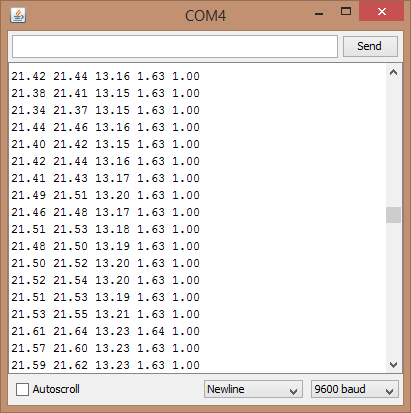
I got the following output when I measured 20W halogen lamp system:
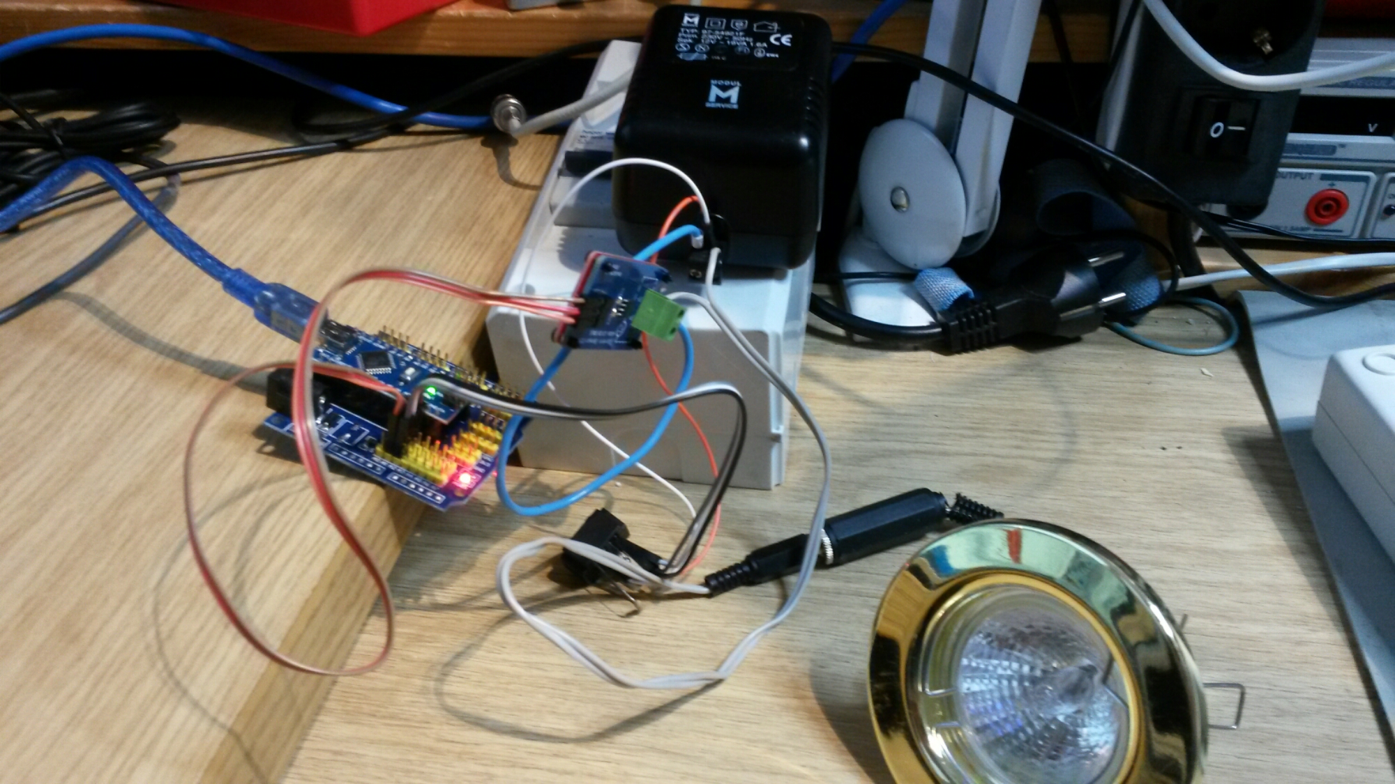
Here is picture of the Arduino Nano + Nano Sensor Shield based test circuit I used:
In this test circuit I measured 12V halogen lamp system current and voltage. For current mesurement I used ACS712 sensor based current measurement sensor module with +-5A current measurement range. For voltage measurement I used a simple voltage divider module (22k ohm from input pin to +5V, 22 kohms from input pin to ground, 120 kohms from AC voltage source to input pin).
One note in plannng to use this power measurements: If you plan to measure mains power, you need to understand all the safety details related to mains power. When testing the circuit, I highly recommend that you have a low voltage test system that you can sefely test and debug your designs (hardware and software). I have used 12V halogen lamp system for this: a traditional 12V transformer gives out safe 12V AC output usually at several amperes, you can control the load easily by turning 12V lamps on/off as needed. When you have debugged your design at safe voltages, you can start thinking of working with higher dangerlous voltages!
Related project pages:
OpenEnergyMonitor building blocks
Watt Meter build walks you through Power Measurement basics
Digital Data from a Cheap Power Meter


128 Comments
Tomi Engdahl says:
https://hackaday.com/2023/10/12/hackaday-prize-2023-ac-measurements-made-easy/
When working on simple DC systems, a small low-cost multimeter from the hardware store will get the job done well enough. Often they have the capability for measuring AC, but this is where cheap meters can get tripped up. Unless the waveform is a perfect sinusoid at a specific frequency, their simple algorithms won’t be able to give accurate readings like a high-quality meter will. [hesam.moshiri] took this as a design challenge, though, and built an AC multimeter to take into account some of the edge cases that come up when working with AC circuits, especially when dealing with inductive loads.
The small meter, an upgrade from a previous Arduino version that is now based on the ESP32, is capable of assessing root mean square (RMS) voltage, RMS current, active power, power factor, and energy consumption after first being calibrated using the included push buttons.
Digital AC Energy Measurement Circuit (Pro)
RMS Voltage, RMS Current, Real Power, Power Factor, Energy KWh
https://hackaday.io/project/193066-digital-ac-energy-measurement-circuit-pro
Tomi Engdahl says:
https://www.electronicdesign.com/technologies/power/article/21275194/analog-devices-powerquality-monitoring-part-2-designing-a-standardscompliant-meter?utm_source=EG+ED+Analog+%26+Power+Source&utm_medium=email&utm_campaign=CPS231005079&o_eid=7211D2691390C9R&rdx.identpull=omeda|7211D2691390C9R&oly_enc_id=7211D2691390C9R
Tomi Engdahl says:
AC Energy Meter Using Arduino With Code and Circuit || Proteus Simulation
https://m.youtube.com/watch?fbclid=IwAR1UaQ9ExTAyYswbq1ekpEOOEGsUMfVcAhzxxJDutLQsRXx-eMHANEl-ML0&v=i81WCkpkqEk&feature=youtu.be
Tomi Engdahl says:
Kotiautomaatioliitäntä
https://www.elenia.fi/tulevaisuuden-energia/sahkonkulutuksen-mittausuudistus/kotiautomaatioliitanta
Elenian mittausuudistuksen uusissa, älykkäissä sähkömittareissa on kotiautomaatioliitäntä, joka mahdollistaa sähkömittarin luennan asiakkaan omaan käyttöön. Tätä uutta ominaisuutta voit hyödyntää palveluntarjoajasi avulla erilaisissa älykkäissä sähköjärjestelmissä, kuten esimerkiksi kotiautomaation ohjaamisessa tai ajoneuvojen latauslaitteissa.
Mittausuudistuksen uudet, älykkäät sähkömittarit on varustettu RJ12-liittimellä, jonka kautta saat hyödynnettyä mittarin mittaustietoa. Vanhemmissa mittareissa tätä ominaisuutta ei ole. Liittimen kautta voidaan lähettää tietoa mittarista ulos, mutta sen kautta ei voi vaikuttaa mittarin toimintaan tai sen sisältämiin tietoihin.
Liitin eli asiakasrajapinta on nimetty eri tavoin eri maissa. Liitintä kutsutaan eri maissa myös nimellä P1-portti, H1-portti sekä HAN-portti, joka tulee Englannin kielen sanoista Home Area Network.
Tyypillisiä mittaustietoja hyödyntäviä järjestelmiä ovat kotiautomaatiojärjestelmät sekä ajoneuvojen älykkäät latauslaitteet.
https://www.elenia.fi/files/5b4d7492d2125ed79a8f1424cd5c4539ba360090/aidonfd-rj12-han-interface-en-v17a.pdf
https://sesko.fi/seskon-suositus-sahkoenergiamittareiden-paikallisesta-h1-asiakasrajapinnasta/
https://sesko.fi/wp-content/uploads/2022/01/Suositus_SK_13-1_H1_asiakasrajapinta_final_2021dec.pdf
Tomi Engdahl says:
https://www.facebook.com/share/p/897Q7HM4fULD1UNB/
Hi all,
I’d like to show my project. It is about measuring the mains frequency.
It might be of interest to people doing some kind of measurement using the ATmega in combination with a Pico W.
I’m just a hobbyist. It is just for fun.
Note the disclaimers about me being in a 50 Hz / 230V domain.
https://github.com/mcjurij/mfm/blob/master/README_en.md#mfm
Tomi Engdahl says:
https://circuitdiagrams.in/arduino-wattmeter/
Tomi Engdahl says:
https://etn.fi/index.php/13-news/16268-tarkkuutta-tasavirran-mittaamiseen
Tomi Engdahl says:
https://etn.fi/index.php/13-news/16874-melexis-kutisti-virta-anturin-ytimettoemaellae-teknologialla-uutta-tehokkuutta
Tomi Engdahl says:
https://hackaday.com/2024/12/02/balancing-balls-with-a-touchpad/
Energy is expensive these days. There’s no getting around it. If, like [Giovanni], you want to keep better track of your usage, you might find value in his DIY energy meter build.
[Giovanni] built his energy meter to monitor energy usage in his whole home. An ESP32 serves as the heart of this build. It’s hooked up with a JSY-MK-194G energy metering module, which uses a current clamp and transformer in order to accurately monitor the amount of energy passing through the mains connection to his home.
Tomi Engdahl says:
https://www.instructables.com/DIY-Smart-Energy-Meter-With-ESP32-Home-Assistant/
Tomi Engdahl says:
ESP32 Powers DIY Smart Energy Meter
https://hackaday.com/2024/12/02/esp32-powers-diy-smart-energy-meter/
Tomi Engdahl says:
https://www.cnx-software.com/2025/01/14/ditronix-ipem-pihat-turns-your-raspberry-pi-into-a-mains-power-energy-monitor/
Tomi Engdahl says:
ESPHome Energy meter reading from P1/HAN port
https://community.home-assistant.io/t/esphome-energy-meter-reading-from-p1-han-port/366457
Tomi Engdahl says:
https://www.xda-developers.com/monitor-your-energy-usage-with-a-raspberry-pi/
Tomi Engdahl says:
https://www.st.com/content/st_com/en/about/customer-success-stories/how-gridspertise-enables-the-smart-meter-revolution.html?ecmp=tt42488_gl_enews_jan2025&mkt_tok=ODU2LVBWUC03MTUAAAGYVMeZH3_uTFw7B2qAg52rT1otmkLD-n3ihbnIY_GWUx2bb0tSgoVe9j_Bxp9-YOgBOREc1wURKImVICl8CSnFnpVMhHQzrtqtprqi_JCwM4dxxc51
Tomi Engdahl says:
Xcrhom T4S WiFi outdoor smart socket features power meter function, Tasmota open-source firmware
https://www.cnx-software.com/2025/02/19/xcrhom-t4s-wifi-outdoor-smart-socket-features-power-meter-function-tasmota-open-source-firmware/
Tomi Engdahl says:
http://omakotikotitalomme.blogspot.com/search?q=HAN
https://www.homewizard.com/fi/kauppa/wi-fi-p1-meter/