Here is story of VTI acceleration sensor interfacing. VTI is an originally Finnish company that has been mostly knows for it’s acceleration sensors. The company has been known with names VTI Hamlin and VTI Technologies, and is now part of Murata.
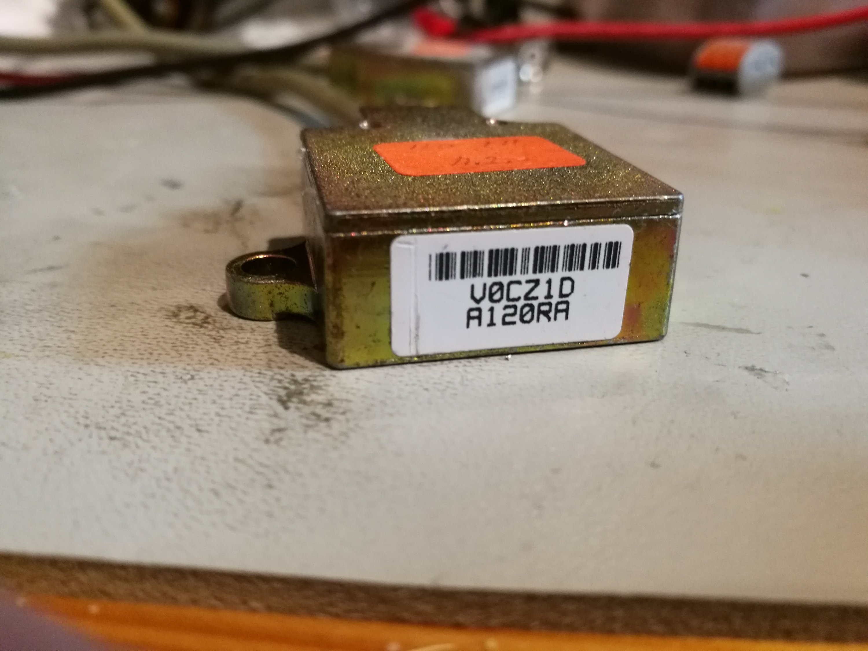
I found some used sensors with three wires. I found no data, some but it looked that those could be acceleration sensors for industrial and/or car applications.
I though that those could be acceleration sensors with analogue output based on earlier information bits found on internet ages ago (Sorry I don’t have link anymore for that). The problem was that I could not find any data sheet of those sensors. The most lacking information was the pin-out, which wire go to which signal and what is the voltage they operate. I did some measurement and testing, but no success, and I did not want to try every combination risking damaging the sensor.
Those sensors were not used for quite a bit of time, until I got some nee ideas to try for wiring from this document:
Back to the Basics – How do I wire my 3-wire sensors?
“Although the sensor technology may differ, all 3-wire sensors are wired the same.A three-wire sensor has 3 wires present. Two power wires and one load wire. The power wires will connect to a power supply and the remaining wire to some type of load.”
“A 3-wire sensor typically is color coded with one brown wire, one blue wire and one black wire.”
This looks promising. My sensor has has three wires with the exactly same colors. Let’s read on the document:
“The brown wire is the +VDC wire that connects to the positive (+) side of the power supply and the blue wire is connected to the common terminal of the power supply; this is the negative (-) terminal that is present on the power supply. The black wire is the output (load) wire of the sensor. 3-wire DC sensors can have a PNP (sourcing) or NPN (sinking) output.“
I continued the testing by applying 5V power between the +VDC and ground connections. The I measured the voltage on the black wire. The voltage about 2.5V DC, and changed somewhat then the sensor was moved. This looks like success. This could be really an acceleration sensor with analogue output.
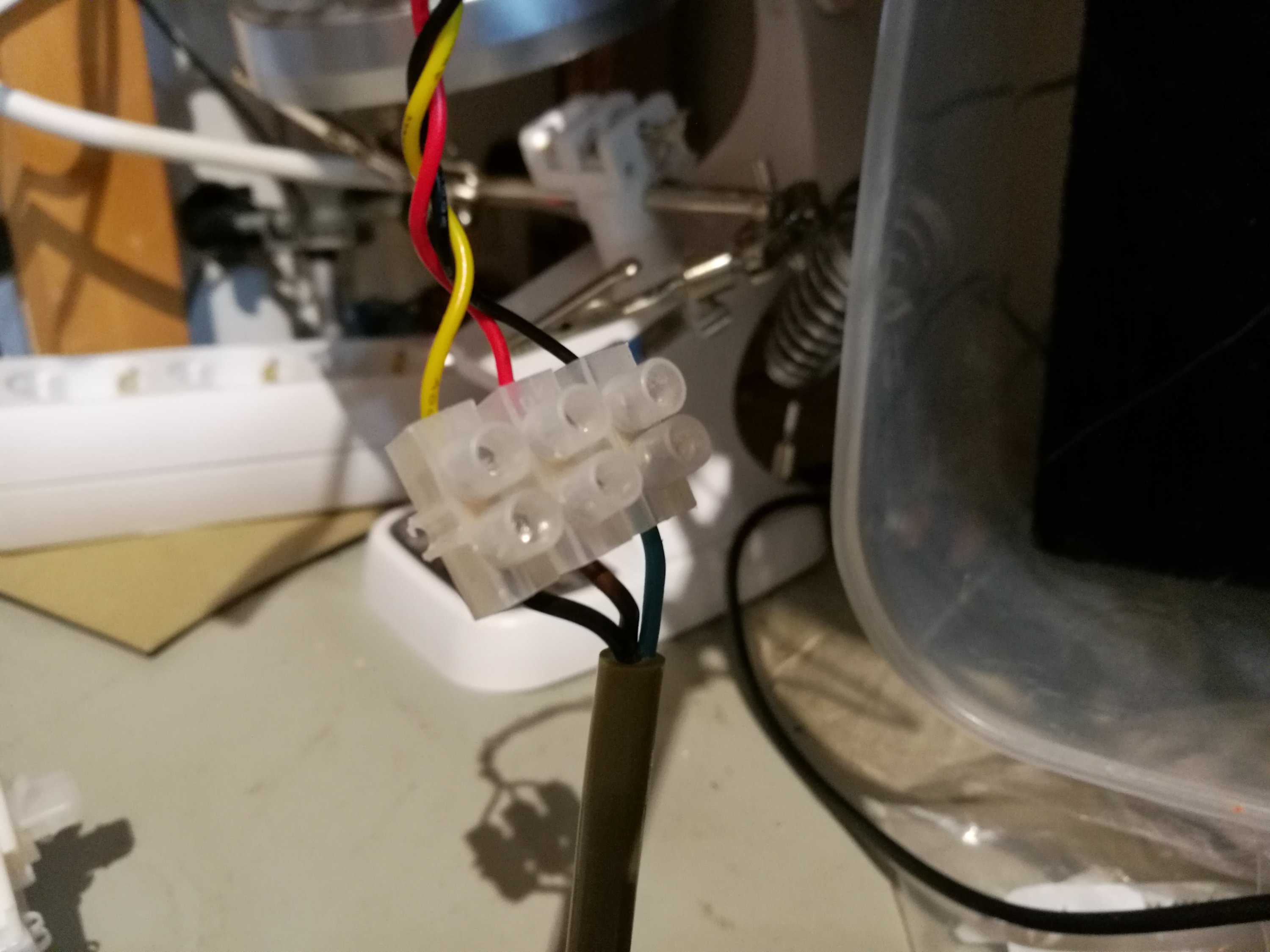
Got working, so wired it to three wire Arduino sensor interface cable so I could wire it to Arduino sensor shield:
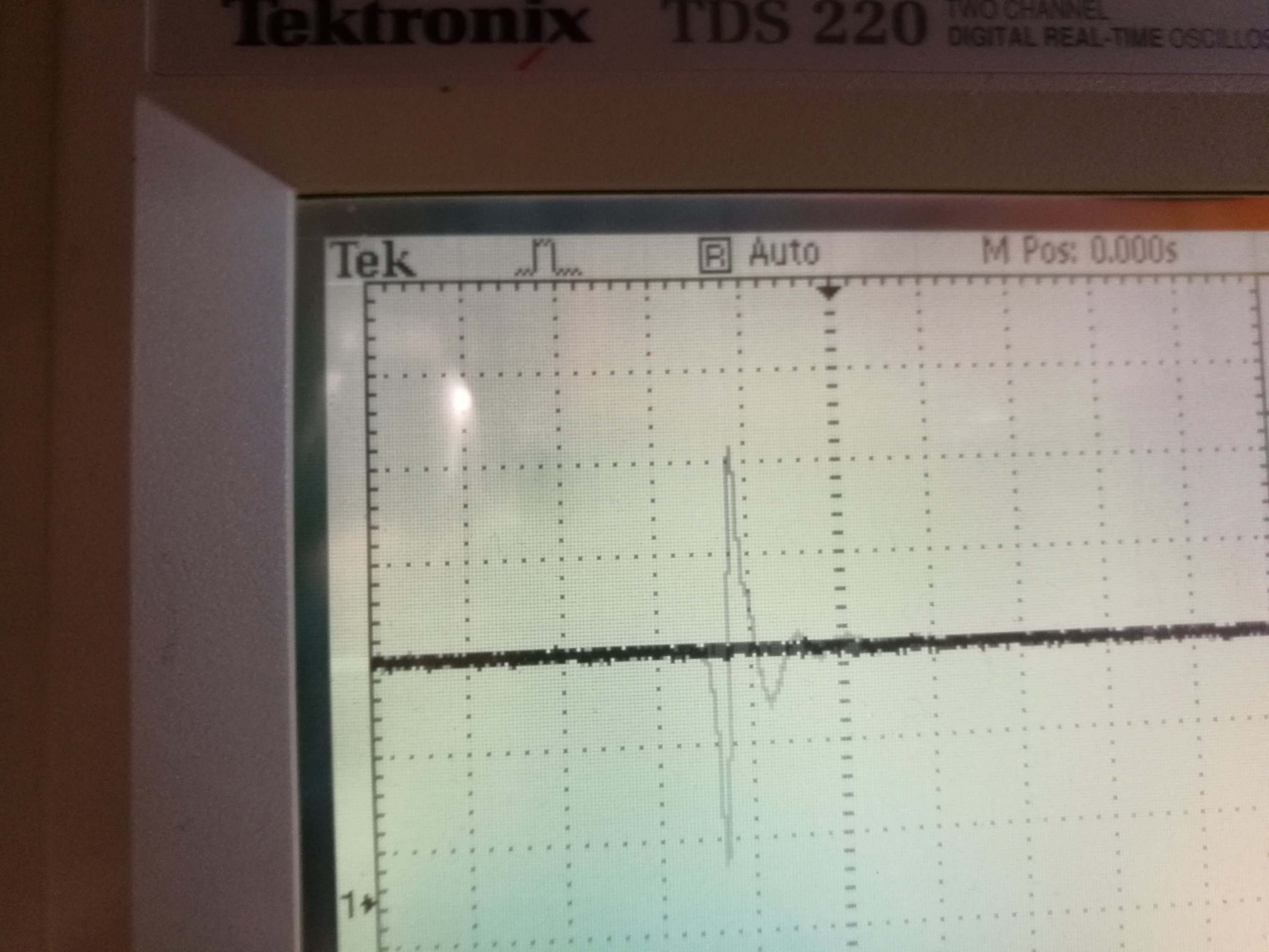
Here is an oscilloscope piture of sensor output when the sensor is tapped with finger:


0 Comments
Be the first to post a comment.