Here is the power supply that came with a cheap MP3 player. It is a power supply that takes in 230V mains power and outputs 5V at USB connector. What is wrong with this power supply?
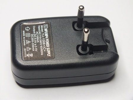
Let’s start with the electromechanical design. The mains connection pins that can be folded in and out at a nice feature, but the mechanical construction of them feels like they can break down quite easily. But the worse it that it can’t be used in many European countries. The pins are so short that they don’t make any contact with the mains power when you try to plug this to Schuko mains outlet. Let’s take a look what is inside.
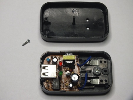
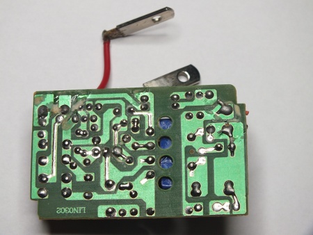
In this picture things look pretty normal. There are quite normal looking components. The PC111 optocoupler between the mains and low voltage side seem to be with specifications up to the job. The transformer looks quite small, but if it is well built it could be up to it’s job. Other components are less critical on electrical safety (more to do with the correct operation and fire safety). But turn on the other side to see the details of circuit board design.
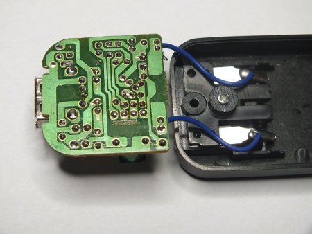
Now I see something to worry about! Take a look at the separation between mains carrying parts and low voltage side: There is less than one millimeter between them (I measured shorted distances to be in 0.5-0.7 mm range). This is not how to build a safe power supply. The creepage distance between the mains voltage and low voltage side should be considerably more for the power supply to be safe. I could not get this arch over with 1 kV from insulation resistance meter, but most probably this kind of design can’t handle much more than this because the typical voltage breakdown in air is approximately 1100 V/mm. Clearly this is not safe to use product!
This kind of power supply should be designed to be double insulated, which means that the insulation between mains and low voltage sides should withstand several kilovolts of voltage. This kind of less than one millimeter creepage distance is clearly not enough for this. Inadequate insulation strength and too small creepage distances seems to be the most common reasons by USB chargers are recalled by Finnish safety authority Tukes. So this kind of bad design seems to be too common.
The typical creepage distance on the circuit board for Reinforced/Double insulation would be 6.4 mm and it should withstand 5000 V RMS (1 min). This 6.4 mm Reinforced/Double insulation creepage is for 300V, Material Group III and Pollution degree 2.
IEC60950-1 MAINS Creepage Requirements for 250V voltage for pollution degree 2 (EN60950, laboratories, office) would be 2.6 mm (material I) 3.6 mm (material II) or 5.0 mm (material III). Most commonly used circuit board materials usually fall in class II and III. The greater the creepage distance, the higher the external safety protection.
According to those standard expect to see in properly designed mains power supply at least 4-5 mm distance between mains side and low voltage side (or well insulating conformal coating). The typical voltage breakdown in air is approximately 1100 V/mm, a 4 mm creepage rate component (not including the internal barrier’s isolation) will break (arc) down at approximately 4400 V.
As an example here is inside view of another mains power supply (one charger that gives out 5V).
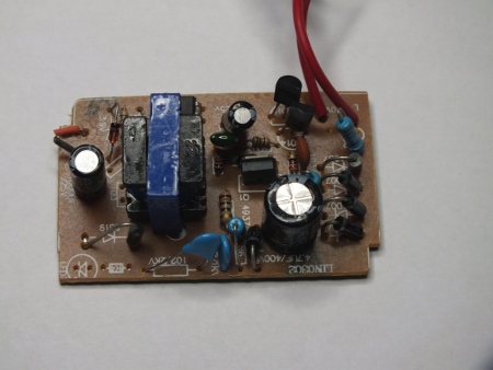
This designs looks better designed. There is clear several millimeters of creepage distance between the mains side and low voltage output side. This looks OK. The critical components between mains and low voltage side in this power supply are the transformer, optoisolator and two capacitors in series (they are rated for 2 kV). They look OK for the given task. This is how to build the circuit board for mains power supply.
19 Comments
Tomi Engdahl says:
PAT adoption allows for safety in electrical testing
European system seeing wider adoption in U.S. markets
http://www.controleng.com/single-article/pat-adoption-allows-for-safety-in-electrical-testing/e5b7cdce91e7bce2df32f67eb3542b4f.html
Testing electrical equipment before it leaves a manufacturing facility, or before work begins on it at a calibration facility, has become increasingly more important in the United States over the past several years. What was once thought of as something that only European countries did has now become a growing trend in the U.S., due to the increased interaction between world markets.
In an effort to meet the needs of all involved, manufacturers of electrical testing equipment have adapted to the regulatory mandates from authorizing agencies around the world to produce testers that facilitate conformance and safety.
Making testing safer
Portable appliance testers, or PAT as they are more simply referred to, have been designed to perform many of these mandated electrical tests quickly, easily, and reliably, while maintaining strict conformance to the specifications and guidelines required by authorizing agencies around the globe.
Using a PAT to perform a testing regime in places like manufacturing plants or calibration facilities helps to identify potential trouble spots in the design, manufacture, and repair of equipment; greatly reduce the risk of using dangerous products; and enhance the quality of products developed by companies that aim to put a respected and trusted brand name on the market.
PATs are very popular in Europe because of the many rules and regulations surrounding electrical safety overseas. European nations enforce regulatory demands on everything from building wiring to individually operated pieces of equipment.
In places like the UK, Ireland, New Zealand, and Australia, electrical appliances are routinely checked for safety. Health and safety regulations in those countries require that electrical appliances be tested routinely to ensure their safety.
In the UK alone, Electricity at Work Regulations (1989) placed a legal responsibility on employers and suppliers to take reasonable steps to ensure that no danger resulted from the use of electrical equipment.
All products that require PAT testing, whether produced or calibrated in the U.S. and sold or shipped back to the European market, must be labeled “satisfactory” and in compliance with European electrical safety regulations and demands. PATs make this stamp of approval possible with a single cable hook-up and a push of a button.
After looking at various testing options, a PAT proved beneficial for Agilent, because it combines the needed technical performance, portability, and short cycle time, while keeping its workers safe.
Electrical testing made easy
Because they are portable by design, most PAT testers are compact and user-friendly with the ability to test quickly, easily, and cost-effectively.
PATs can perform manual or automatic testing and users can select PASS/FAIL limits to speed up individual tests and simplify results. Most offer simple push-button operation for direct access to tests via a keypad. Some PATs have the ability to download test data onto a PC
PATs are valuable because they easily help companies save time and money by determining if a piece of equipment is faulty before turning it on.
Tomi Engdahl says:
Something WiFi This Way Comes; Wicked Device Unveils Wildfire
http://hackaday.com/2013/11/28/fail-of-the-week-how-a-cheap-usb-ac-adapter-might-indirectly-burn-your-house-down/
This Fail of the Week will remind our readers that every project they make, no matter how small they might be, may have big consequences if something goes wrong. Shown in the picture above is an oven that [Kevin] tweaked to perform reflow soldering.
The oven control board [Kevin] designed is powered by USB and uses simple ON/OFF temperature control.
He discovered that his temperature reading was not correct, and that swapping the USB AC adapter with another resolved the problem.
The mains adapter he was using is non-branded and he guesses that the 5V rail is super dirty.
Tomi Engdahl says:
Why it is not a good idea to buy counterfeit power supply:
iPad charger teardown: inside Apple’s charger and a risky phony
http://www.righto.com/2014/05/a-look-inside-ipad-chargers-pricey.html
Apple sells their iPad charger for $19, while you can buy an iPad charger on eBay for about $3. From the outside, the chargers look the same. Is there a difference besides the price? In this article, I look inside real and counterfeit chargers and find that the genuine charger has much better construction, power quality, and most importantly safety. The counterfeit turns out to be a 5 watt charger in disguise, half the power of a genuine charger.
One safety difference is obvious: the Apple charger has much more insulation.
the counterfeit charger is much simpler
Both chargers use resistors to put special voltages on the USB data lines to indicate the charger type, using Apple’s proprietary system. (This is why iPads say “Charging is not supported with this accessory” with some chargers.)
Safety probably isn’t something you think about when you plug in your charger, but it’s important.
The UL regulations[14] require safe separation between the high voltage and the low voltage. This is measured by creepage – the distance between them along the circuit board, and clearance – the distance between them through air. The regulations are complex, but in general there should be at least 4mm between high-voltage circuitry and low-voltage circuitry.
the genuine iPad charger’s circuit
This gap of 5.6mm provides a comfortable safety margin.
The creepage distance on the counterfeit charger board below is scary – only 0.6 mm separation between low and high voltage.
this board is unsafe. If you use the charger in a humid bathroom and a drop of water condenses across the 0.6 mm gap, then zap!
The key safety requirement of the transformer is to separate the high-voltage windings from the low-voltage secondary winding, and the counterfeit charger fails here.
The triple-insulated wire is an important safety feature that keeps the high voltage out even if there is a flaw in the insulating tape and in the wire’s insulation.
The real charger provides much more power with much less noise
Is the Apple charger worth the price?
Apple’s charger is expensive compared to other chargers, but is a high quality product. You should definitely stay away from the cheap counterfeit chargers, as they are low quality and dangerous. Non-Apple name brand chargers are generally good quality according to my tests, with some better than Apple.
In any case, the iPad charger is an impressive piece of engineering with a lot of interesting circuitry inside. The counterfeit charger is also impressive in its own way – it’s amazing that a charger can be manufactured and sold for such a low price (if you don’t care about safety and quality).
Tomi Engdahl says:
PCB Design Tech Guide
A wide collection of PCB Layout Design Guidelines and Considerations for better Performance, Reliability, and Manufacturability.
http://www.pcbtechguide.com/2009/02/creepage-vs-clearance.html#.U3NSbihM0ik
The greater the creepage distance, the higher the external safety protection. As always, the amount of it distances required for a given mode depends on the end system specification.
Tomi Engdahl says:
Creepage distance for PCBs handling line voltage AC?
http://electronics.stackexchange.com/questions/22796/creepage-distance-for-pcbs-handling-line-voltage-ac
Tomi Engdahl says:
Pollution degree 2 applies to the vast majority of ITE (information technology equipment) – degree 3 is for stuff that is subjected to significant external contamination.
http://www.creepage.com has handy calculation tools
Tomi Engdahl says:
CALCULATING SPACING BETWEEN PCB TRACES FOR VARIOUS VOLTAGE LEVELS
CIRCUIT BOARD LAYOUT GUIDELINES
http://www.smps.us/pcbtracespacing.html
For example, in the U.S. for most mains-powered or battery-powered information technology equipment, the minimum allowed PCB spacing should be determined from UL 60950-1 2nd Edition Tables 2K, 2L, 2M or 2N. These tables specify so-called clearance and “creepage” distances for various grades of insulation as functions of working voltage, pollution degree, PCB material group and coating.
The distances provided by IEC and UL actually greatly exceed the spacing necessary for proper operation of the devices. This was done in order to provide increased protection against electric shock. For the circuits whose locations do not require electric shock protection, spacing between printed circuit tracks can be made smaller.
Based on the experiments, UL specified withstand voltage of 40 volts/mil or about 1.6 kV/mm in their UL796 Standard for Printed Wiring Boards.
It is interesting to note that many major power supply manufacturers in their low-power off-line designs are widely using 500-800V MOSFETs in TO220 package operating at 400V and higher. With this package you can get about 30 mils spacing between the pads, while the documents would require at least 100 mils. Even if you spread the leads on the PWB, you can’t do anything with 50-mil spacing between the TO220 leads along the surface of the package.
Also note that technically the insulation requirements given in UL 60950 are for frequencies up to 30 kHz. So far, 60950-1 2nd Edition permits to use the same requirements for frequencies above 30 kHz until they will figure out what to do about it.
Tomi Engdahl says:
PCB CREEPAGE CALCULATOR
http://pcbdesign.smps.us/creepage.html
The creepage requirements depend on the insulation material group, pollution degree and working voltage. For a given circuit and application, these requirements are always greater than or equal to the clearance. Our calculator provides the values from Table 2N of UL60950-1 2nd Edition. Note that these values apply to functional, basic and supplemental insulations. For reinforced insulation you need to double the results.
This widget is for a preliminary estimation only. For a final design decision you need to work with actual standard which has many nuances.
Tomi Engdahl says:
Tips to Avoid Arcing December 19, 2006
http://circuitcalculator.com/wordpress/2006/12/19/tips-to-avoid-arcing/
I recommend you check out the calculator at http://creepage.com. Distances should be checked by setting up rules in the PCB layout tool so errors will be flagged. The creepage path may be increased by placing slots in the PCB or adding a physical barrier.
If the distance must be small, special coatings or potting may be needed. Voids or air bubbles in the insulator material can form corona that can eat away at the insulator, so vacuum potting or vacuum deposited coatings are sometimes used.
Tomi Engdahl says:
Clearance for 230V design
The high voltage from low voltage tracks clearance depends on the product type (consumer, automation, military, aerospace ….). It also depends on the altitude that product functions.
The track width depends on the current flow.
6mm or so IIRC, but if you open up a cheap switching phone charger or laptop power supply, they don’t come even near that.
IIRC for a product I designed 10 years ago it was described in the EN60335 (Check Semko if youre in Sweden). Some distances for 2 products I designed :
Product 1)
Powering from L,N and PE class I product
Distance between L and N 2mm
Distance between L/N and PE 3mm
Distance between L/N and user-accessable voltage 3mm
Product 2)
Powering from L and N, no PE, class II product
Distance between L and N 2mm
Distance between L/N and user-accessable voltage 8mm
(No guarantee on these values – they came from a rather far part of my memory)
At least you can use multiple of 1 mil for your voltaje…
you need 230v clearance so use at leaset 23mil clearance.
and for your current you can use multipe of 1mil for 100 milliamps.
if you need 1A you should use at leaset 10mil track withd….
Respect to EN61010, if you use a plastic enclosure and there is no metallic part accessible, then you can use 6mm between AC mains related voltage and ‘low voltage user side’. 3mm between AC tracks.
Source: http://www.avrfreaks.net/index.php?name=PNphpBB2&file=viewtopic&t=88585
Tomi Engdahl says:
The chargers at
http://www.banggood.com/Dual-USB-2-Ports-EU-Plug-LED-Light-Wall-Charger-For-IPhone-IPad-p-924538.html
seem to have quite small insulation distances on the circuit board as well..
Tomi Engdahl says:
Cheap USB chargers are ‘a real danger’
Australian warning follows one death
http://www.theinquirer.net/inquirer/news/2352494/cheap-usb-chargers-are-a-real-danger
AN AUSTRALIAN Fair Trading Office has warned people of a “real and present danger” that they have invited into their homes, the cheap USB charger.
Cheap knock-off device chargers are associated with several things, especially dangerous incidents.
Many times a simple charging process has turned a piece of hardware into a smokey melted lump and on some occasions more damage has been done.
Stowe, reacting to a report that a knock-off charger started a fire that killed a woman, said, “These devices pose a serious risk of electrocution or fire,” and recommended that no one buy or sell them.
Tomi Engdahl says:
Safety alert – USB style chargers
http://www.fairtrading.nsw.gov.au/ftw/About_us/News_and_events/Media_releases/2014_media_releases/20140626_safety_alert_usb_style.page
Tomi Engdahl says:
Horrific USB power supply fault. (Electrocution risk.)
https://www.youtube.com/watch?v=3Hdn0MuCK_0
Oddly it does appear to be relatively sensibly designed inside, but this one has a serious manufacturing fault that suggests others from the same run may also pose a risk of serious electric shock.
Sadly, this just reinforces my doubts about the poor separation in many of these small transformers.
I’d rather have split bobbin transformers even if it meant efficiency taking a slight hit.
Tomi Engdahl says:
Crappy PSU analysis
https://www.youtube.com/watch?v=T88ej64aXUM
Pulling apart a too-cheap-to-be-true PSU. Guess what… it was too cheap.
Inside a reasonable quality Chinese PSU
https://www.youtube.com/watch?v=1F3XlFI1JBo
frank says:
Hi,
We use an off line application powered the circuit with 230Vac+20%=276Vac after the rectifier diode we have 390Vdc. For a double insulation, where I have 276Vac creepage distance is 6.4mm, after the diode (390Vdc) 8mm. that’s right or I have to use 8mm everywhere. Thanks.
Tomi Engdahl says:
I can’t give generic answer for this based on information you have given.
The needed creepage distance depends somewhat on the materials used, environment and the safety standard you need to follow.
There are some differences on the demands on different standards.
Tomi Engdahl says:
Don’t buy cheap death-wish chargers
https://www.youtube.com/watch?v=rwEh4jsVew0
While it’s commendable that Apple introduced style to humble things like USB chargers, it’s not so commendable that the inevitable clones tried to jam all the required circuitry into a tiny plug and sell it for a pound/dollar/euro.
This charger was bought from a high street store in Glasgow. An independent Asian pound shop (UK dollar store) that I actually like a lot, but this shouldn’t really be on their shelves.
Most high profile pound shops charge around £2 for a basic charger and they are generally OK. But even the bigger names like Pound World (Now called One Below) fell foul of selling dangerous chargers. Their current offering does look safer, but Poundland is still the king for better quality tech.
I personally use an IKEA USB charger for all my tech. (Not a sponsor.) With a genuine Motorola charger for battery capacity tests. (Also not a sponsor.)
I’ve said it before and I’ll say it again. Don’t buy cheap power supplies. Only buy them from prominent brands with a reputation to protect. That includes ASDA and Walmart. A USB charger is an essential part of modern living, and plugging your £$€1000 smartphone/tablet into a £$€1 charger is basically a death wish for you and your tech.
ultimateshop login says:
What’s up, the whole thing is going nicely here and ofcourse every one is sharing information, that’s
truly good, keep up writing.