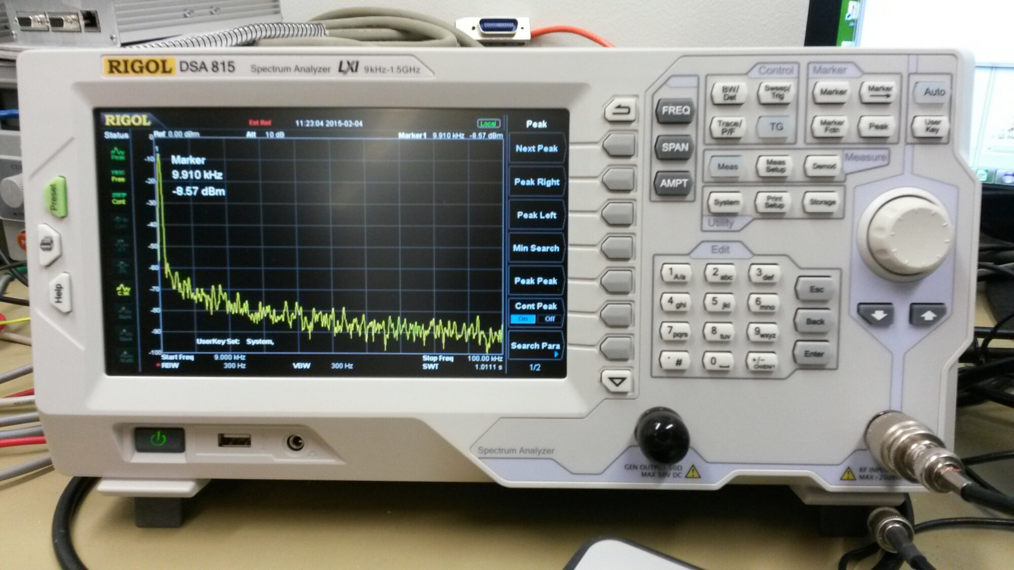
I have already written a few posts on AD9850 DDS testing. Here are some more testing. I had possibility to test my signal generator circuit with Rigol DSA 815 RF spectrum analyzer.
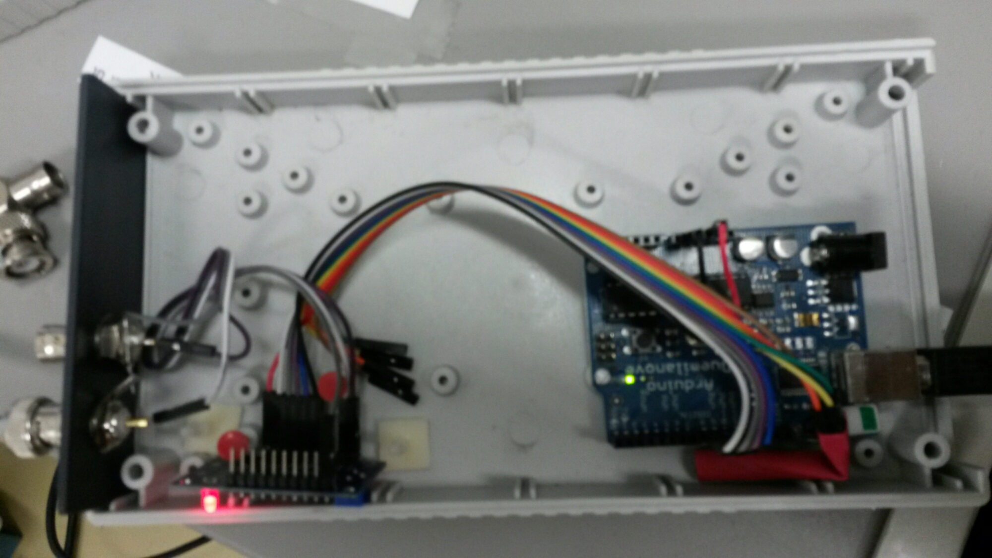
I improved my test circuit from previous tests by putting it inside case. I also replaced Arduino UNO with Arduino model with FTDI USB interface IC that works on modern Windows PC without need to install extra drivers.
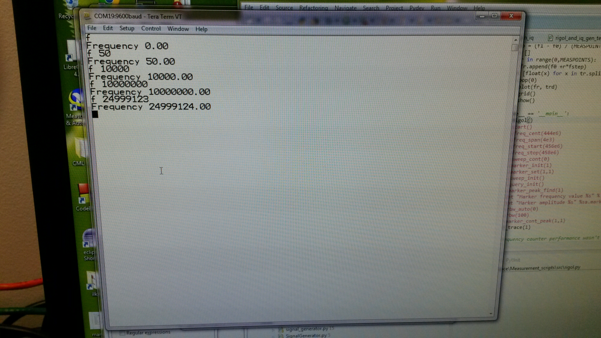
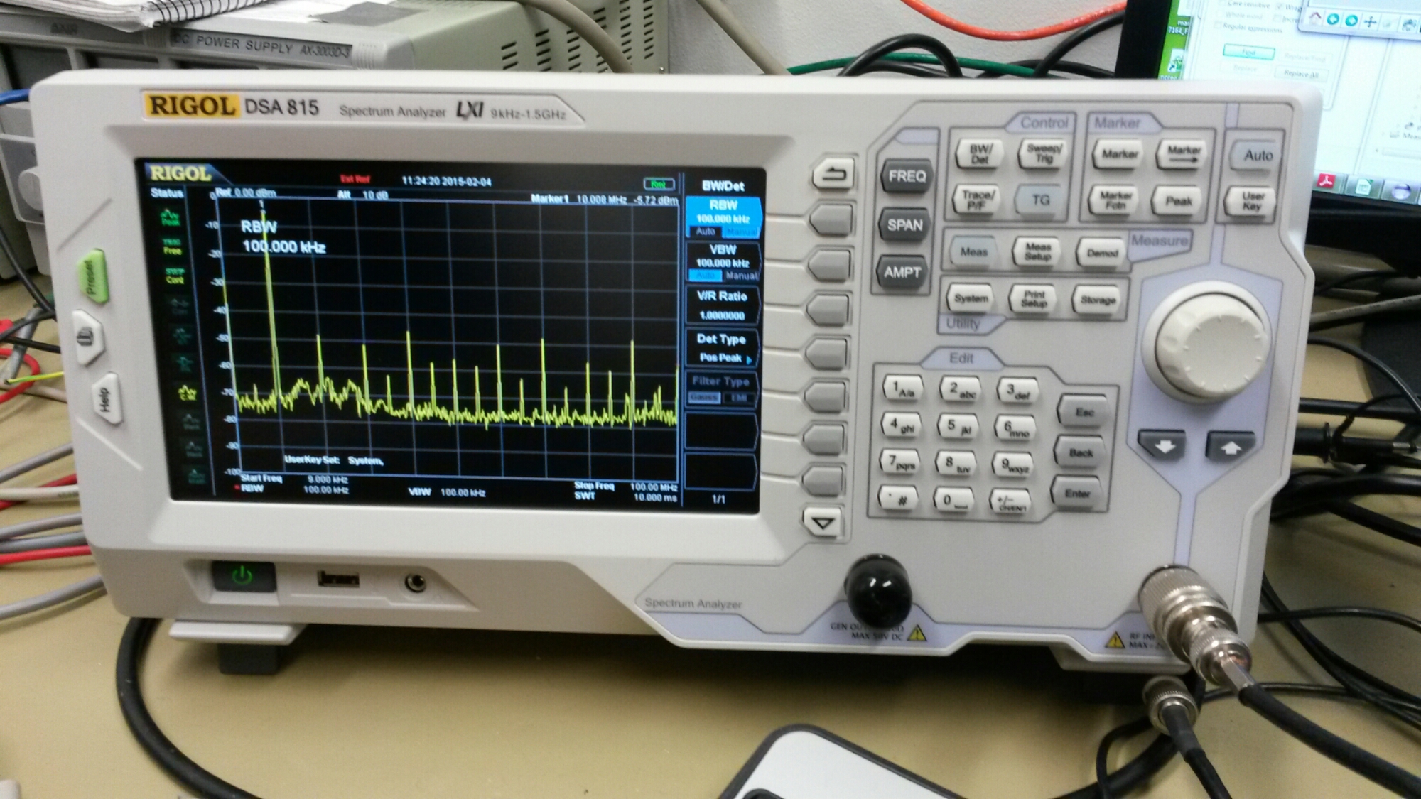
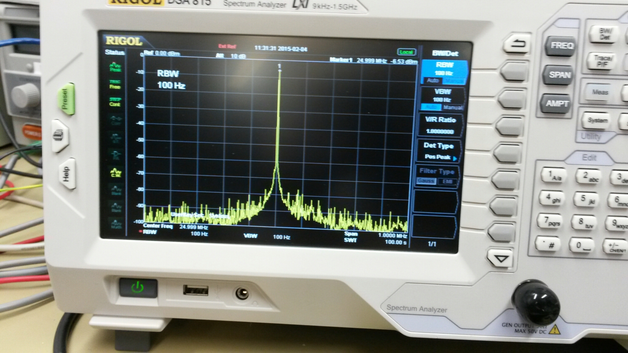
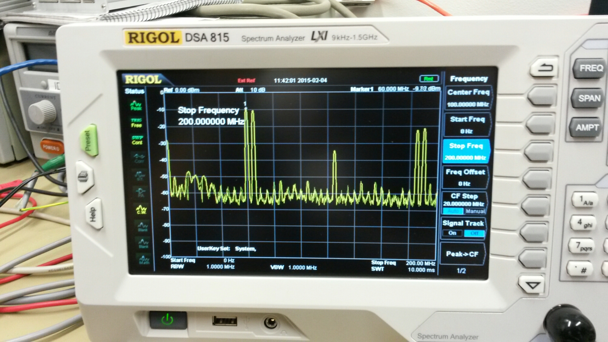
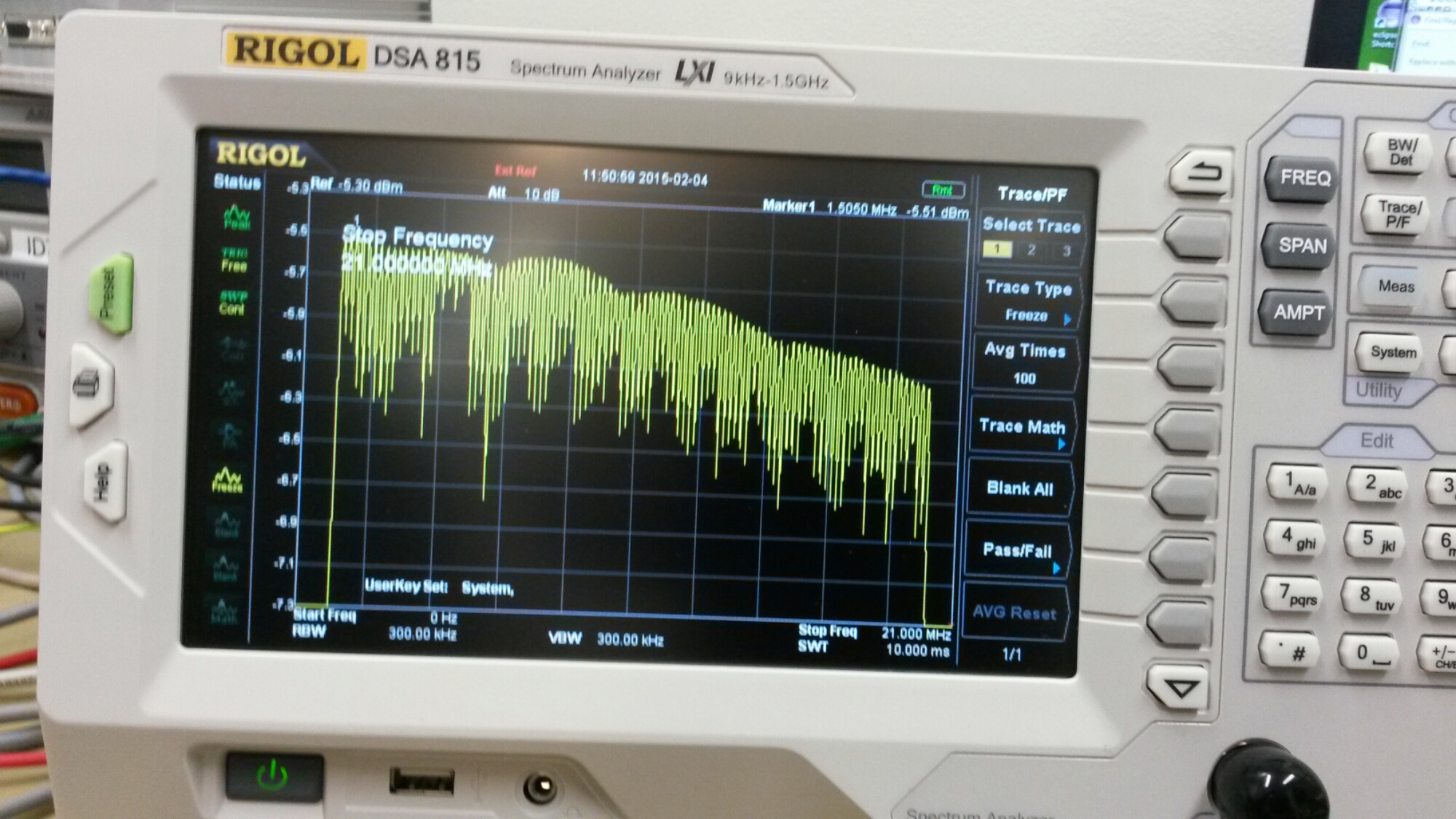
Here are some measurement results.
Signal seemed to be quite clear up to around 30 MHz, and with somewhat more harmonics up to promised 40 MHz. The IC seemed to give out some signal up to slightly over 62 MHz (quite much harmonics at highest frequencies).
Posted from WordPress for Android
10 Comments
Tomi Engdahl says:
Testing a filter using a Rigol spectrum analyzer
https://www.youtube.com/watch?v=1Cbv2gUExEQ&list=UULzhNnl9a0-RZz7VyTrkcHw&index=42utm_source=EEWeb&utm_medium=TechCommunity&utm_term=2014&utm_content=Content&utm_campaign=RIGOL
This video explains how to use the tracking generator (TG) option of a spectrum analyzer to characterize a filter.
Tomi Engdahl says:
Troubleshoot Radiated Emissions to 1000 MHz
http://www.eetimes.com/author.asp?section_id=36&doc_id=1326613&
Many product designers and EMI engineers are using the popular Rigol DSA815 spectrum analyzer for EMI troubleshooting and pre-compliance testing. I’d like to demonstrate the instrument settings and measurement features I most commonly use when troubleshooting radiated emissions in the 30 to 1000 MHz region. You’ll find these useful for either near field probing or testing emissions using a nearby EMI antenna.
Advanced radiated emissions troubleshooting setups with the Rigol DSA815
http://www.edn.com/electronics-blogs/the-emc-blog/4439359/Advanced-radiated-emissions-troubleshooting-setups-with-the-Rigol-DSA815
Tomi Engdahl says:
Measure Antenna VSWR Using a Spectrum Analyzer
http://www.eeweb.com/company-blog/rigol_technologies/measure-antenna-vswr-using-a-spectrum-analyzer/
Antennas are a popular topic among radio enthusiasts. The Rigol Spectrum Analyzer VB1020 option and utility kit are good tools to help improve antenna design and characterization. This combination provides complete measurement of antenna resonance frequency, antenna bandwidth, return loss, reflection factor, and voltage standing wave ratio (VSWR)
Tomi Engdahl says:
WLAN Sinus Generator
https://hackaday.io/project/12887-wlan-sinus-generator
A Sinus (0-40MHz) generator controlable via WLAN, using AD9850 and ESP8266.
I will build a Wlan controlable Sinus Generator (0 – 40 MHz, 1Hz Resolution) using an ESP8266 WLAN Module as MCU and WLAN Bridge and an AD9850 DDS Module.
The Generator will be controlable via an Android app and a computer Program. And it will has an API for writting your own Applications.
The Generator will also have an ADC input, so you can use it as an wireless voltage meter and plotter. The input is rectified so you can use it in combination with the Sinus DDS Generator as a wobbler (so you can create filter curves of your HF filters).
do9jhb/WiFi-Sinus-Generator-android
The Repository for the WiFi-Sinus-Generator Android App
https://github.com/do9jhb/WiFi-Sinus-Generator-android
The ESP8266 Code for my WLAN DDS Sinus Generator
https://github.com/do9jhb/WiFI-Sinus-Gen
Tomi Engdahl says:
Arduino Network Analyzer
Network Analyzer on an Arduino Shield which covers from 0-72MHz.
https://hackaday.io/project/10021-arduino-network-analyzer
The network analyzer shield uses an Analog Devices AD9851 DDS chip clocked at 180MHz which will output a sine wave at any frequency from 0Hz and 72MHz. The DDS output is filtered with a Butterworth LPF and then passed to a two transistor amplifier. The shield will output approximately 0dBm (maybe 1-2dBm if you turn the Pot up; may get distortion, though) into 50 Ohms. The output and input connectors are SMA. The power detector is an Analog Devices AD8307. It’s inputs are terminated with a 50 Ohm load. There is no filtering on the input of the power detector so the chip is responsive from very low frequencies all the way up to 500MHz.
Tomi Engdahl says:
OpenGen – OSHW handheld wave gen
https://hackaday.io/project/2136-opengen-oshw-handheld-wave-gen
OpenGen – AD9850 DDS module based waveform generator which generates sine & square waves up to 42.5MHz and is completely self
OpenGen is a DDS waveform generator which can generate sine and square waves put to 42.5MHz. It is in a rugged handheld case and has a built in power supply and Arduino-compatible microcontroller to allow it to function independent of a PC.
OpenGen can output sine and square waves from 3kHz to 42.5MHz in increments of 0.0291Hz. The square output triggers from the sine so they cannot be different frequencies. There is a load switch (pushbutton controlling a relay) for each output to disconnect a load easily. The analog parameters (sine amplitude & offset, square duty cycle) are adjustable to an 8-bit resolution (2^8=256 steps).
Tomi Engdahl says:
Optimizing Arduino and the AD9851 DDS signal generator
http://www.edn.com/design/test-and-measurement/4441389/Optimizing-Arduino-and-the-AD9851-DDS-signal-generator?_mc=NL_EDN_EDT_EDN_today_20161219&cid=NL_EDN_EDT_EDN_today_20161219&elqTrackId=343c83b2dc8d40dda27e10f9be9e44fb&elq=d7ba377ef607436089271baa9171b745&elqaid=35219&elqat=1&elqCampaignId=30769
Arduino has taken the product “maker” world by storm and one of the more popular Arduino modules is the Analog Devices AD9851 DDS waveform generator. An Internet Web search for “Arduino DDS” showed more than 100,000 results, while the same video search turned up many dozens of videos. Internet forums are filled with discussions related to two specific issues. One issue is that the output amplitude is not constant with frequency, requiring a level control loop. The second issue is that the distortion gets pretty horrific, particularly at higher output frequency settings. In this article, we’ll show how to correct these issues, as well as providing some additional tips for improving the quality of the output.
While this article concentrates on the AD9851 device, Analog Devices produces many others that operate in a similar fashion. The devices combine a clock reference with a digital divider and a phase locked loop to provide a sinewave output with very fine resolution. In the case of the AD9851, the digital divider is 32 bits and the clock frequency is typically 125 MHz. This results in a frequency resolution of approximately 30 milli-Hz. A single resistor, Rset controls the current output level and therefore the output voltage level.
popular AD9851 DDS module from Ebay is shown connected to an Arduino UNO via the Picotest J2130A DC blocker. The Arduino is used to set the output frequency of the AD9851.
Tomi Engdahl says:
Arduino Powered Portable Function Generator
https://hackaday.com/2018/09/03/arduino-powered-portable-function-generator/
For those worrying that [Faransky] is relying on the PWM functionality of the Arduino Nano to generate waveforms, have no fear. At the heart of the device is a AD9833 waveform generator; with the Arduino, rotary encoder, and 16×2 LCD providing an interface to control it over SPI.
Unfortunately, the AD9833 doesn’t have a way to control amplitude, something which is pretty important in a function generator. So [Faransky] uses a X9C104P 100KOhm 8-bit digital potentiometer as a voltage divider on the chip’s output.
Portable Function Generator on Arduino
https://www.instructables.com/id/Portable-Function-Generator-on-Arduino/
Tomi Engdahl says:
10kHz-40MHz AD9834 Scalar Network Analyzer
http://alloza.eu/david/WordPress3/?p=1138
Tomi Engdahl says:
AD9833 Function Generator
Build a function generator with an Arduino Nano and a AD9833 Programmable Waveform Generator module.
https://www.hackster.io/john-bradnam/ad9833-function-generator-180317