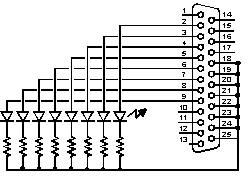
Product type: 8-channel semiconductor relay module that connects to PC parallel port, comes with controlling software
Product home page: http://www.kemo-electronic.com/en/module/m125/
Manufacturer: Kemo Electric
http://www.kemo-electronic.com/
Price: around 33 Euros
Place whee bought: Bebek http://www.bebek.fi/
Manufacturer product description:
Relay module for switching up to 8 different appliances, lamps or motors according to a computer program (software is enclosed). The installed solid-state-relays may switch voltages up to 40V and loads up to 0,4A (DC) or 0,2A (AC). The module is operated at the printer port LPT1.
Comments:
This kit works. It has eight opto-isolated outputs that can be easily controlled though data pins on the PC parallel port. The isolation works as claimed and can control light loads nicely. The device can be controlled with the software that comes with the card, or many other third party software that can control parallel port pins. If you are looking for simple optoisolated output for PC, this could be a good product even if you do not use the original software. If you want to write your own software, my instructions at http://www.epanorama.net/circuits/parallel_output.html can be used to implement your own software.
The manufacturer lists the necessary technical data on the output capablilities, but I could not find anywhere anythign how good the isolation between the PC and output is. It woudl be a good to know the isolation voltage to check if this is useful in any demanding application.
Other downsides are (the manufacturer mentions this), that the outputs are not specifically protected agains overcurrent (can be damaged if yu try to push too much current through them) and that the module cannot be repaired if you happen to damage it.
Other things that I did not specifically like are that the output connector and the connector that plugs to PC are bith 25 pin D connector, male goes to PC LPT1 and the output connector is female. The downside of using similar connectors on both sides could be potantially dangerous on systems that are put up and put back to boxes often by different people. You could accidentally forget to put the module between the parallel port before the controlled load (the connector would plug in nicely) with damanginf and expensive consequences: damaged parallel port on your PC.
I have used this module as part of interface that interfaced the PC parallel port output to a lighting control system (0-10V interface) successfully. The voltage and current range looks so that the module outputs would interface nicely to 24V industrial audiomation systems.
And there is also possibility to control small relays or small loads directly (in those applications I would think adding some etra ptotection to avoid frying the module in case of wiring errors or spike caused by inductive load would be a good idea...)
The control software is designed to work with "normal" PC parallel ports. The software works with paralle ports on the PC motherboard, and also works with extra parallel ports on old computer that had ISA bus. The software that comes with the card (like many other similar parallel port controlling software) does not seem to work with extra parallel ports that plug to PCI bus or USB (those are accessed somewhat differently at hardware level).