Basic: Want to wire switches to 14-seg display
5 posts • Page 1 of 1
Basic: Want to wire switches to 14-seg display
Hello all, this is my first post. I need help with a car project I have going. I want to wire a segment display to microswitches mounted on the shifter in my car to display the characters 1-6, N, and R. I have tried reading up on how to accomplish this but I am a n00b when it comes to electronics; my main problem is that I just can't quite grasp how to integrate the parts into a circuit. From what I've researched I will need 8 microswitches (or at least 6 for the main 6 gears), a 14 segment display, a BCD, resistors, and some wire/breadboard. Could someone please help me understand how to build this? Recommended parts and how-to circuit advice would be great, my car is in pieces and I need to get this done ASAP...thanks for the help, sorry I'm new to circuits 
- cargeek
- Posts: 3
- Joined: Mon Jul 27, 2009 1:44 pm
Re: Basic: Want to wire switches to 14-seg display
I know seven segment display technology, and that's common.
First the question would have been what is "14-seg display" you are referring to but Wikipedia answered that for me
http://en.wikipedia.org/wiki/Fourteen-segment_display

One simple way to control whatever combination of display segments is this.
You have a separate switch for each position you want to indicate.
You make sure that only one of them is active at one time passing power though (more than one "on" gives strange display results of both characters for them combined)
I expect you have LED display.
Add a suitable resistor for each segment.
Connect the common pin to +power or - depending on display polarity.
From each switch wire a diodes that pass current to those segments that need to be on (diodes wired to free end of segment current limiting resistors). In this way when switch is turned on the segments where diodes connect to become active.
In the end you have just a large set of resistors, few switches and a large set of diodes that do the display controlling.
First the question would have been what is "14-seg display" you are referring to but Wikipedia answered that for me
http://en.wikipedia.org/wiki/Fourteen-segment_display

One simple way to control whatever combination of display segments is this.
You have a separate switch for each position you want to indicate.
You make sure that only one of them is active at one time passing power though (more than one "on" gives strange display results of both characters for them combined)
I expect you have LED display.
Add a suitable resistor for each segment.
Connect the common pin to +power or - depending on display polarity.
From each switch wire a diodes that pass current to those segments that need to be on (diodes wired to free end of segment current limiting resistors). In this way when switch is turned on the segments where diodes connect to become active.
In the end you have just a large set of resistors, few switches and a large set of diodes that do the display controlling.
- Tomi Engdahl
- Site Admin
- Posts: 1839
- Joined: Mon Oct 20, 2003 6:15 pm
- Location: Espoo, Finland
Re: Basic: Want to wire switches to 14-seg display
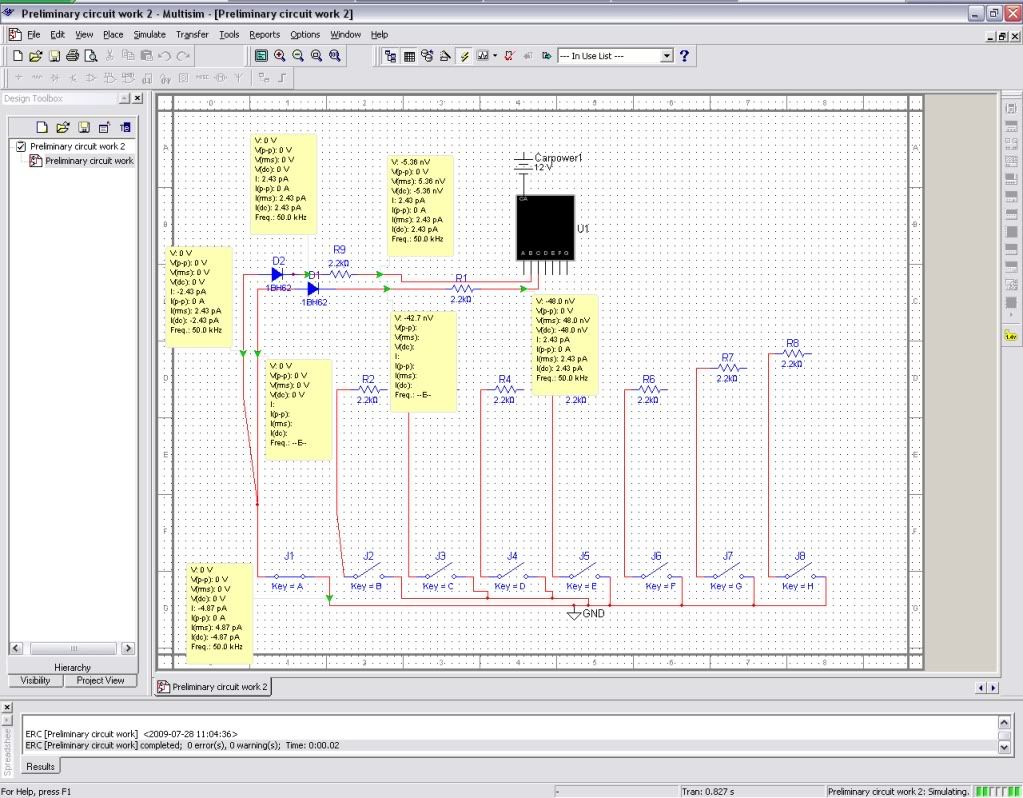
Ok, so how does this preliminary set-up look?
DC/GND (car is normal 12v system, should I be using AC or DC?)
2.2kΩ
1BH62 diodes (I just picked the first one, I have no idea which diode to use)
I've tried all different types of orientations of the diodes and I've tried 3 separate displays. Anyone have a 15-seg display pinout diagram?

DC/GND (car is normal 12v system, should I be using AC or DC?)
2.2kΩ
1BH62 diodes (I just picked the first one, I have no idea which diode to use)
I've tried all different types of orientations of the diodes and I've tried 3 separate displays. Anyone have a 15-seg display pinout diagram?

- cargeek
- Posts: 3
- Joined: Mon Jul 27, 2009 1:44 pm
Re: Basic: Want to wire switches to 14-seg display
Your setup looks like a start for the project.
By the way you have drawn the diodes on the wrong way on your drawing.
They should pass the current from display to switch that connect to ground, not the other way around.
By the way you have drawn the diodes on the wrong way on your drawing.
They should pass the current from display to switch that connect to ground, not the other way around.
- Tomi Engdahl
- Site Admin
- Posts: 1839
- Joined: Mon Oct 20, 2003 6:15 pm
- Location: Espoo, Finland
Re: Basic: Want to wire switches to 14-seg display
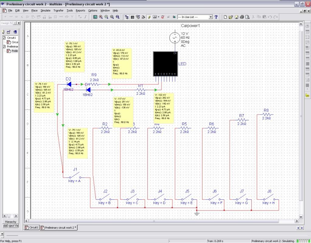
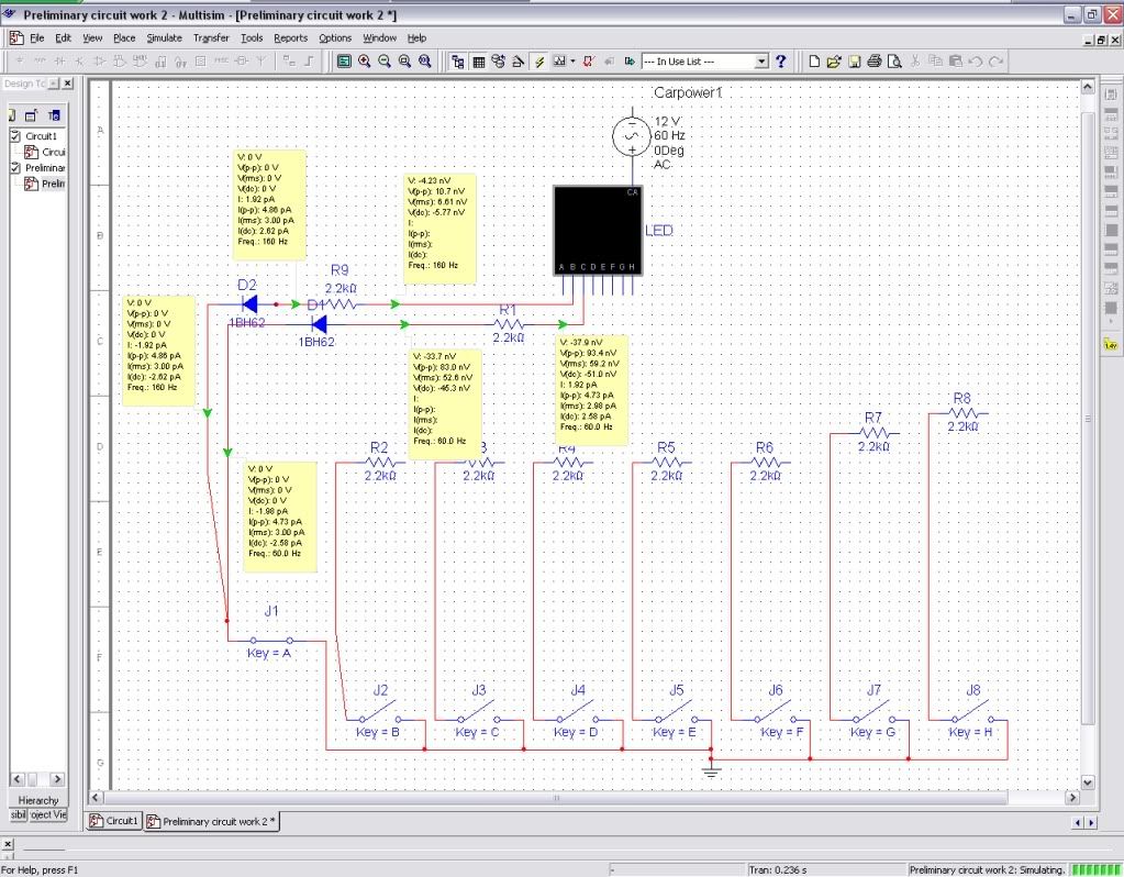
Thanks for the continued help  Anyway, here is my setup, which should (?) work...1st pic is "off," the 2nd is "switched on." Here are as many specs as I have:
12v AC power
7-seg LED (I'll use a 14 seg one I get past the voodoo aspect of circuits ) - On current: 5mA, Vf: 1.66volt
2.2kOhm resistors
generic diodes
ground
Should I use DC with a DGND instead for power? Is there anything obviously wrong? I'm dying to see the LED "1" pop up
Off

Switched on

12v AC power
7-seg LED (I'll use a 14 seg one I get past the voodoo aspect of circuits
2.2kOhm resistors
generic diodes
ground
Should I use DC with a DGND instead for power? Is there anything obviously wrong? I'm dying to see the LED "1" pop up
Off

Switched on

- cargeek
- Posts: 3
- Joined: Mon Jul 27, 2009 1:44 pm
5 posts • Page 1 of 1
Return to Circuits and Components
Who is online
Users browsing this forum: No registered users and 3 guests

