Low Voltage Preamplifier
Description:
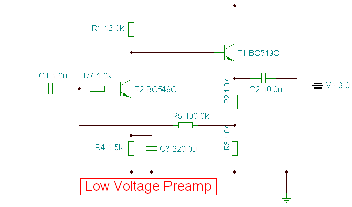
A low voltage preamplifier optimised for 3 Volt operation.
Description:
This is a special low voltage version of my audio preamp. T1's emitter voltage is biased close to half supply voltage (1.5V) to allow for maximum output voltage swing. Both transistors are direct coupled and have closed loop feedback to aid temperature stability.
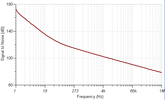
T2 realises the amplifiers full voltage gain, and for low noise operation, T2 collector current is about 70uA. T1 merely buffers T2 and operates in emitter follower mode providing a good low output impedance. The overall S/N ratio measured at the output is shown below:
Signal to Noise Ratio
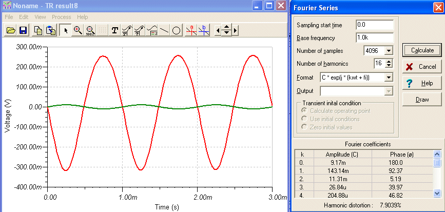
Capacitor C3 decouples the emitter resistor of T2. Without C3 the gain of T2 would be approximately R1 / R4. With C3 the gain of T2 is now R4 in paralell with the input impedance of T1 / the small signal emitter resistance of T2. The overall voltage gain of the circuit is around 28 times as shown below. Harmonic distortion is about 8%.
Harmonic Distortion
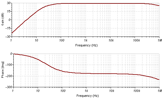
Frequency response is flat from 50Hz to around 200KHz. Phase change across this range varies little, see bode plot below.
Bode Plot
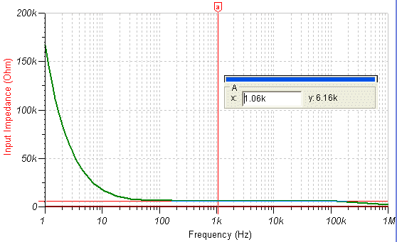
One drawback of this circuit is that the input impedance is fairly low. This is because the input of T2 is low and has C3 decoupling the emitter. The inclusion of R7 in series with the base of T2 raises input impedance slightly. A plot of input imedance versus freqency response is shown below.
Input Impedance
The output impedance is very low, around 66 ohms as shown in the plot below. Note that this is a preamp and therefore designed to feed into a power amplifier not drive direct loads directly.
Output Impedance
Content sourced from Zen Schematics
Circuit:Andy Collinson


