How to draw VeroBoard Layouts
Veroboard Layouts
By Ron J
The layouts are drawn using the Paint programme. They are built up by placing component shapes onto a veroboard pattern. Working with the 2X magnification is generally the most convenient. To give yourself more room, go to "View" and close down the "Colour Box" and the "Status Bar". You can identify the various tools by placing the mouse pointer over the toolbox button and leaving it there for a second or two.
Component leads and links are drawn using the "Line" tool. Make the lines double thickness by clicking on the second example from the selection which appears just below the Tool Box. If you hold down the "Shift" key as you draw, the line will be straight.
Use the "Select" tool to choose the component you require. Hold down the "Ctrl" key and use the mouse to drag off a copy. Make its background transparent by clicking the lower of the two yellow buttons which appear below the Tool Box. If you right click on the selected component you can change its orientation using "Flip/Rotate" from the context menu.
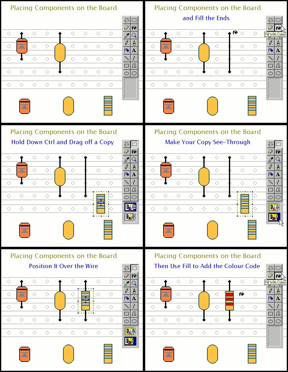
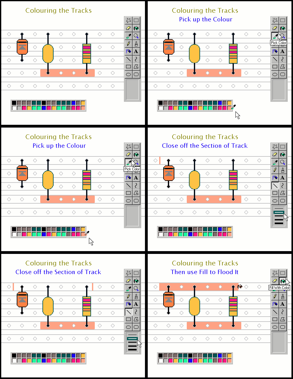
The "Fill With Color" tool is used to show connections to the board. It is also used to give values to the resistors and to indicate the active sections of the copper strips. To change colours use the "Pick Color" tool together with the extended replica of the "Color Box".
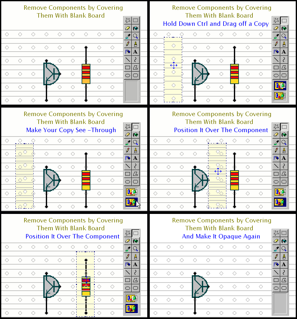
The models of some of the components come with a little of the vero pattern. They may be accurately placed onto the board by lining up the holes. Take the trouble to position everything carefully. If you get it wrong go to "Edit" and click "Undo". If necessary, remove components by covering them with a section of blank board.
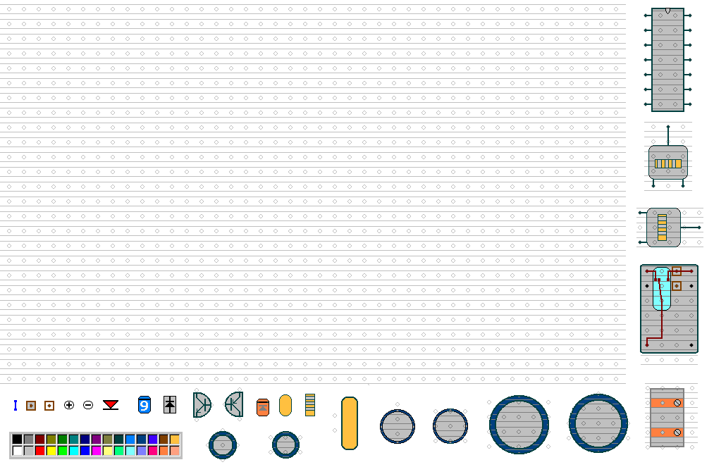
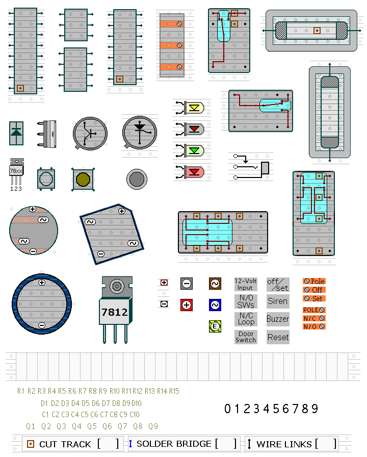
The "Vero" template includes models of the most common components. There are more shapes on the accompanying "Parts" template. These may be imported individually using "Copy" and "Paste". Of course, you are free to rearrange, alter or add to the models to suit your own requirements.
Paint is not very good at handling gifs. You MUST begin by converting the "Vero.gif" into a Bitmap. Open it using Paint. Then save it as a Bitmap. Close it down again; and open the new Bitmap version. To avoid corrupting your Bitmap template, save it once more using whatever name you want your project to have.
This article covers the basic drawing techniques. However, Paint includes other features which you will find useful; especially if you want to draw new component models.
You can download for free, excerpts from the latest edition of "The Secret Guide to Computers" by Russ Walter.
His account of how to use the Paint programme is both clear and concise. You'll find it about halfway through the chapter on "How to use Windows....."
More Components
Content sourced from Zen Schematics


