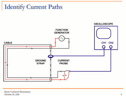
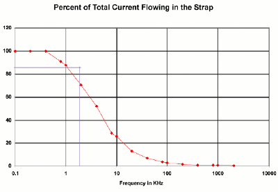
Some days ago read Things Every Electrical Engineer Should Know about EMC slide set by Todd H. Hubing Michelin Professor of Vehicular Electronics Clemson University. I must say that it is an interesting slide set to check. It is a short 25 slide set that introduces EMC fundamentals and ground loops. Here is one fact that is not often presented clearly elsewhere:
Current takes the path of least impedance!
> 100 kHz this is generally the path of least inductance
< 10 kHz this is generally the path(s) of least resistance


4 Comments
school grants says:
What a great resource!
Tomi Engdahl says:
Successful PCB grounding with mixed-signal chips – Part 3: Power currents and multiple mixed-signal ICs
http://www.edn.com/design/analog/4396382/Successful-PCB-grounding-with-mixed-signal-chips—Part-3–Power-currents-and-multiple-mixed-signal-ICs?cid=Newsletter+-+EDN+on+Analog
Tomi Engdahl says:
Get the fix on common EMC problems
http://edn.com/electronics-blogs/rowe-s-and-columns/4434850/get-the-fix-on-common-EMC-problems
“I keep running into the same EMC problems over and over,” EMC Engineer Kenneth Wyatt told an audience
“EMC problems appear because many designers don’t understand how to design for EMC,” said Wyatt. He then spent 90 minutes discussing the causes of EMC problems such as gaps in return planes, cable resonance, shielding, and bonding as well as troubleshooting techniques and tools. Many of the topics Wyatt discussed are covered in The EMC Blog and in his new book EMI Troubleshooting Cookbook for Product Designers: Concepts, Techniques, and Solutions.
Gaps in return planes are one cause of the common-mode currents that produce unwanted emissions.
Wyatt then showed some examples of products that failed compliance tests and why they failed.
Wyatt explained why LCD displays can be a source of unwanted emissions because LED drivers use LVDS (low voltage differential signaling), which clocks the data at rates approaching 500 MHz and use fast edge speeds. These high frequency, fast edges, tend to couple common-mode currents onto the display cable and housing, which creates emissions that can escape from gaps between the display and enclosure.
Poor bonding of cable through enclosures is another problem. Wyatt showed an industrial application where not only wasn’t a cable shield connected to a return or reference location, but cables were routed through an enclosure, leaving gaps.
A near-field probe and an oscilloscope using an FFT show how a gap in a return plane can create emissions when carrying digital signals.
Slides
https://webinabox.vtools.ieee.org/wibp_site_files/index/CH01036#13
Tomi Engdahl says:
Don’t be the victim of electrical noise and EMI
http://www.controleng.com/single-article/dont-be-the-victim-of-electrical-noise-and-emi/abea90dba205b59e1441292286849104.html
Electromagnetic interference (EMI) and radio frequency interference (RFI) in automated machinery can negatively affect operations, and there are options to reduce or remove it. Learn the consequences of electrical noise and benefits of quieting things down.
Even with proper precautions, some electromagnetic interference (EMI) and radio frequency interference (RFI) will be present in automated machinery, so components should have appropriate shielding and filtering such that interference will not negatively affect operations.
There are common mode and differential mode components to EMI noise. Common mode EMI noise is transmitted on multiple conductors at the same time and in the same direction on all conductors from source to receiver. Most pulse width modulated (PWM) ac drives produce high frequency common mode noise. Differential mode noise is induced on a conductor and travels in the opposite direction as it does on the grounded conductor. This is similar to a complete circuit with a separate supply and return path for the EMI.
Often depending on the frequency, EMI is emitted as conducted or radiated EMI.
There are many sources of EMI in industry
There are several types of components often affected by EMI in industrial applications (see Table 2). Encoders rely on low-level signals from rotating equipment and are thus susceptible to EMI.
Electrical noise near analog signals and measurement instrumentation often can cause symptoms including unexpected voltage spikes and ripple or jitter causing incorrect or nonrepeatable readings. This occurs more often in voltage-based signals such as 0-10 V dc. The integrity of a current-based 4-20 mA signal is less susceptible to noise.
With communication networks and components, electrical noise symptoms almost always include loss of communication or errors in reading or writing data. And with programmable logic controllers (PLCs) and other microprocessor-based components, symptoms can include loss of communications, faults or failure in the PLC or processor, discrete inputs or outputs triggering unexpectedly, and analog inputs or outputs reporting incorrect values.