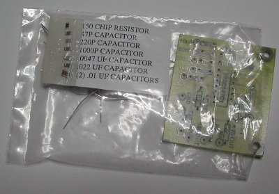
My Time Domain Reflectometer (TDR) circuit has been available as kit made by Far Circuits. The kit consists only of circuit board and components needed to build the circuit in a small plastic bag (you need to download the building instructions).

The original circuit design is from my web page and Far Circuits added 5V regulator and designed the circuit board.
I have written some information about the TDR kit earlier, but now you have more. I just finished building my own kit sample some days ago.

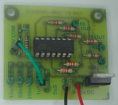
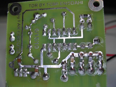
Around half of the components on the kit are SMD components and half of the components are traditional through-hole soldered components. I was pretty easy to build, no problems there. I used lead free solder to build the circuit even though it might not be optimal solder if some components contains lead.
I first soldered the SMD components to clean circuit board using pinbypin method. Then I assembled the through hole components to their places and solder them.


The kit worked well but with some reduced performance compared to my original design. The original circuit design used pretty high speed 74AC14 IC, but this kit I received used a slower speed 74HC14 IC. That was the actual IC that was in component bag instead of 74AC14 as listed on the component list.
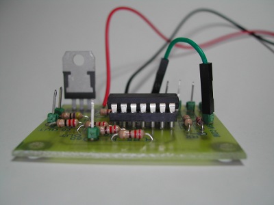
Things seen on the pictures not included on the original kit: IC socket, pins to connect wire to, jumper wire connected between two pins to select the pulse length and the wired feeding power to the circuit.
NOTE: The first kit versions were shipped with 74HC14 IC. According to Farcircuits the newer kit versions are shipped with 74AC14 IC.
64 Comments
Tomi Engdahl says:
Ask Hackaday: Is Our Power Grid Smart Enough To Know When There’s No Power?
https://hackaday.com/2020/06/23/ask-hackaday-is-our-power-grid-smart-enough-to-know-when-theres-no-power/
Bouncing Pulses Along Your Power Lines
Time domain reflectometry is an extremely simple process that relies on the property of a traveling waveform to bounce off the end of a transmission line and be reflected back to its originator. It’s a standard lab experiment for electronic engineering students that can easily be replicated with a pulse generator, a coil of cable, and an oscilloscope. Adjust the ‘scope to see the end of the generated pulse, and there a short time later will be its reflection. The time between the end of the sent pulse and the arrival of the reflection is the time it has taken to travel the length of the cable and back again, so from that the length of the cable can be calculated.
Since the pulse will reflect from any faults, the distance to the fault can also be worked out. Once the breaker has been triggered by the fault the electricity company can measure the distance, and send out a repair team to fix it. That’s exactly how an El Segundo steam plant located a fault in ten miles of buried cable.
Find And Repair A 230kV 800Amp Oil-Filled Power Cable Feels Like Mission Impossible
https://hackaday.com/2015/07/27/find-and-repair-a-230kv-800amp-oil-filled-power-cable-feels-like-mission-impossible/
Finding out the location of the fault itself was quite a feat. It involved time-domain reflectometry (inconclusive), ultrasound, and radar (didn’t work) and then using an Impulse Generator-Tester (Thumper) which got them pretty close to the defective segment. What pinpointed the problem was a bunch of car batteries and some millivoltmeters. They hooked up car batteries to both ends, tapped the cable at several points and knowing the drops and resistance of the cable, got within a few feet of the fault. Finally, X-Ray equipment was brought in.
The failure was attributed to “TMB”, short for Thermal Mechanical Bending. TMB causes the cable to wiggle in place due to load surges. This eventually causes insulation failure due to abrasion against the pipe and separation of the many layers of paper tape.
Tomi Engdahl says:
https://hackaday.com/2016/02/21/retrotechtacular-transmission-lines/
Tomi Engdahl says:
https://www.instrumart.com/assets/Megger-TDR-Applications.pdf
Tomi Engdahl says:
https://forum.arduino.cc/t/tdr-time-domain-reflectometer-concept-on-the-right-track/179362
Tomi Engdahl says:
I bought 1000 meters of wire to settle a physics debate
https://www.youtube.com/watch?v=2Vrhk5OjBP8
I constructed the Veritasium electricity thought experiment in real life to test the result.
If you were watching my community posts a month ago, the day that Derek over on Veritasium posted his video about electricity misconceptions, you saw me obsess over that problem a bit too much and immediately use it as the excuse I’ve been looking for for years to own my own oscilloscope. Instead of two light-seconds of wire, I used about 3 light-microseconds of wire, but it was PLENTY to resolve exactly what is happening in this circuit. I hope you enjoy the analysis!
Tomi Engdahl says:
Practical Use of the NanoVNA Time-Domain Reflectometer
https://www.youtube.com/watch?v=rEFOgp2RYu0
In this video I use the TDR (low-pass step function) transform feature of the NanoVNA V2 to verify that I have an outside antenna problem on my roof, and not a coax cable problem located inside. This serves as a field-expedient way to identify the location of an antenna system problem that can be easily done with any NanoVNA.
0:00 Preface
1:22 Background Info and TDR Setup
4:52 SOL 1-Port Calibration
5:54 TDR Distance to Fault Measurements
9:20 Pre-Maintenance Return Loss Checking
11:07 Post-Maintenance Results Summary
12:50 End
Tomi Engdahl says:
#1254 CD40106 aka 74C14
https://www.youtube.com/watch?v=FExN8ZaufCI
Episode 1254 chip of the day
CD40106 Hex Schmidt Trigger Inverter
Viewer comments:
The 74HCU04 which is the un-buffered version of the ‘HC04, is praised as capable of low phase noise when used as crystal oscillator. Also, these un-buffered cmos inverters are quite versatile as they behave quite linearly when biased as analog inverter amplifiers.
Be aware that if you order a cheap CD40106 from China you may get a repainted 74HC14A instead. If you plan on using it at 5V or less this is fine, but unlike the 74Cxx and CD4000 series chips which have an absolute maximum VCC rating of 18V, the 74HC ones are only good up to 8V. I designed and built an automotive control circuit using a “CD40106″ and couldn’t figure out why it worked perfectly on the bench (using a 5V supply) but kept failing completely after just a few hours of use in the car at 12V (or 13.8V). It took me a while and a half-dozen fried “40106′s” to figure out that my 40106 wasn’t actually a 40106. The vendor had simply rebadged 74HC14 chips as CD40106/74C14. Caveat Emptor.
Tomi Engdahl says:
EEVblog 1439 – Analysing Veritasium’s Electricity Misconceptions Video
https://m.youtube.com/watch?v=VQsoG45Y_00&feature=youtu.be
Tomi Engdahl says:
How Wrong Is VERITASIUM? A Lamp and Power Line Story
https://m.youtube.com/watch?v=iph500cPK28&feature=youtu.be
Tomi Engdahl says:
Understanding VSWR and Return Loss
https://www.youtube.com/watch?v=BijMGKbT0Wk
This video provides a basic introduction to voltage standing wave ratio (VSWR) and return loss, and explains how these measurements are used in radio frequency applications.
Tomi Engdahl says:
The speed of light in vacuum is 2.998 × 10⁸ m/s, which is approximately equal to 1 ft/ns. In most coaxial cable and many twisted pair wires, the speed of an electrical signal is about 2/3 of this. This also applies to most untwisted “normal” speaker cables as well.
Tomi Engdahl says:
https://download.tek.com/document/Understanding-Applying-TDR-Primer_48W-74128-0.pdf