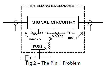
A Ham’s Guide to RFI, Ferrites, Baluns, and Audio Interfacing is an interesting tutorial on understanding and solving RF interference problems. To solve interference problems, we must understand them. The document describes many EMC issues well. Almost all RFI problems we describe as “RF in the shack” have pin 1 problems as their root cause!
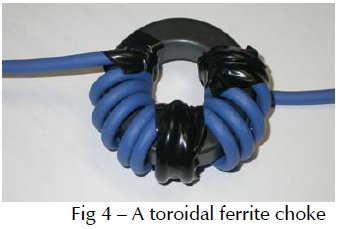
Ferrites can be a very effective tool for eliminating RF interference between systems. To use them effectively, you need understand them. The document gives you the basic information you need on ferrites and gives many practical application examples for using them.


18 Comments
Tomi Engdahl says:
https://vk6ysf.com/balun_1-1.htm
Tomi Engdahl says:
Using Baluns and RF Components for Impedance Matching
https://www.coilcraft.com/getmedia/ebe04fb9-dede-42c0-bcd2-ddfa3f66994a/Doc1077_Baluns_and_Impedance_Matching.pdf
Tomi Engdahl says:
How to make a 4 to 1 balun cheap and easy
https://www.youtube.com/watch?v=7lYY7nkKrWo
Tomi Engdahl says:
All About Baluns (Ask Dave #73)
https://www.youtube.com/watch?v=GMeOMwf2DJU
Tomi Engdahl says:
Baluns for 88–108 MHz
http://ham-radio.com/k6sti/balun.htm
Coiled-Coax Balun
You can make a simple current balun by coiling coaxial feedline in a particular way. At self-resonance the coil acts as a parallel trap whose high impedance inhibits unwanted shield current.
To construct the balun, mark RG-6 coax with tape at two spots 27″ apart (26″ for RG-59). Coil the coax into three turns with the marks aligned. Secure the coil with dark, UV-resistant tie wraps in several places so that adjacent turns everywhere touch. Route the coax leads straight away from the coil.
A current balun is most effective when placed at the feedpoint where shield current is highest. When that’s not possible, form the feedline into a second balun a quarter wavelength (30″) away from the first. Multiple spaced baluns are particularly effective at reducing shield current induced by asymmetrical coupling to the antenna, as may occur when the antenna is vertically polarized.
Ferrite Choke Balun
Passing coax through ferrite material increases its common-mode impedance without affecting its differential impedance. A Laird 28A0807-0A2 snap-on, split-ferrite core, stocked by Arrow, Mouser, and Digi-Key, is simple to install. Rated impedance is 348Ω at 100 MHz. It will accomodate quad-shield RG-6.
The plastic closures of a split-ferrite core may become brittle and fail when flexed after long outdoor exposure. Tape or tie-wrap a broken housing to ensure that the ferrite halves remain firmly joined. The ferrite material does not seem to degrade outdoors.
A nonsplit ferrite core, installed before terminating the cable, is more robust than a split core. A Fair-Rite 2643625202 from Arrow, Mouser, and Digi-Key has a rated impedance of 361Ω at 100 MHz (Ken Wetzel measured 330Ω). It will accomodate quad-shield RG-6.
300Ω Ferrite Baluns
Most 300Ω consumer baluns use two bifilar windings on a binocular ferrite core interconnected as shown. When driven at the 75Ω terminals, these baluns produce equal voltages of opposite phase with respect to the coax shield at the 300Ω terminals. Conversely, voltages common to the 300Ω terminals cancel at the 75Ω terminals. The purpose of the winding short may be to disable the bifilar winding while retaining its stray reactance for symmetry. With input and output shorted, common-mode impedance typically is less than 20Ω.
Some baluns omit the winding short. These devices produce unequal voltages at the 300Ω terminals but tend to equalize current in the parallel lines. A single turn at the center of the core and two wires connected to the coax shield instead of four identify a current balun. Common-mode impedance typically is 250Ω.
Balun Cascade
You can increase the common-mode impedance of a 300Ω voltage balun by following it with a 75Ω current balun. The cascaded common-mode impedance is the sum of that for each balun.
A halfwave coaxial line that inverts signal phase makes a low-loss 300Ω voltage balun.
300Ω L-Network Balun
An L-network followed by a current balun can match and isolate a 300Ω load. When made with a ferrite choke, this balun has the low loss of a halfwave coaxial balun but is more compact.
Improper Baluns
Over the years, many kinds of baluns have been proposed and built that don’t actually work. If you see a ground symbol in a balun schematic, beware. It may just indicate circuit common. But if it is an external connection, the designer has almost certainly confused RF and DC ground. Far from the earth’s surface, no non-radiating RF current sink seems to exist. This includes the antenna boom, which will simply radiate any current a balun directs to it. You’ll find several examples of improper baluns here.
http://dg7ybn.de/Symmetrising/Symmetrising.htm
Tomi Engdahl says:
FERITE BALUN 1.8 – 30Mhz
https://www.qsl.net/g4wpw/balun
Tomi Engdahl says:
Matching 50Ω to 75Ω
http://ham-radio.com/k6sti/match.htm
Tomi Engdahl says:
Simple HF Baluns for 50/75 Ohm Systems
http://www.iw5edi.com/ham-radio/1942/simple-hf-baluns-for-5075-ohm-systems
Tomi Engdahl says:
Turn 75 Ω TV “Rabbit Ears” with a balun into a 50 Ω dipole antenna
https://ham.stackexchange.com/questions/9897/turn-75-%CE%A9-tv-rabbit-ears-with-a-balun-into-a-50-%CE%A9-dipole-antenna
Tomi Engdahl says:
HF Antennas impedance matching.
http://zr6aic.blogspot.com/2014/01/hf-antennas-impedance-matching.html
Tomi Engdahl says:
Make a wideband antenna matching transformer
https://www.onetransistor.eu/2015/10/wideband-antenna-matching-transformer.html
This matching transformer can be used for VHF and UHF reception (from 50 to about 800 MHz). The input is 300 ohms balanced and the output is 75 ohms unbalanced, ready for coaxial cable connection. I found out that a device similar to what is presented here is used in commercially available antenna preamplifiers with 300 ohms input.
Tomi Engdahl says:
75Ω TDK Surface Mount Balun Transformer
https://fi.rsdelivers.com/product/tdk/atb2012-75011-t/75%CF%89-tdk-surface-mount-balun-transformer/8319305?cm_mmc=FI-PLA-DS3A-_-google-_-CSS_FI_EN_Power_Supplies_%26_Transformers_Whoop-_-(FI:Whoop!)+Chip+Baluns-_-&matchtype=&pla-343302609258&s_kwcid=AL!7457!3!516783619880!!!g!343302609258!&gclid=EAIaIQobChMIwKaY5qGy8AIVikiRBR2bjgU-EAQYASABEgLoLvD_BwE&gclsrc=aw.ds
Tomi Engdahl says:
nanoVNA-H – measure ferrite core permeability
https://owenduffy.net/blog/?p=16124
Measuring ferrite beads
https://groups.io/g/nanovna-users/topic/35413448
Tomi Engdahl says:
How to measuring ferrite core efficiency vs frequency
https://ham.stackexchange.com/questions/15033/how-to-measuring-ferrite-core-efficiency-vs-frequency
Tomi Engdahl says:
How to Identify an Unknown Ferrite Core
https://www.youtube.com/watch?v=Q95Vwk3kZok
#84: Basics of Ferrite Beads: Filters, EMI Suppression, Parasitic oscillation suppression / Tutorial
https://www.youtube.com/watch?v=81C4IfONt3o
Tomi Engdahl says:
https://www.fair-rite.com/determining-the-material-of-a-ferrite-core/
Tomi Engdahl says:
Rolling Your Own:
building antenna splitters that perform better than most commercial units
http://www.dxing.info/equipment/rolling_your_own_bryant.dx
Tomi Engdahl says:
electromagnetic interference is true. I have experienced it many times in many systems and equipment.
“How much it affects a speaker cable, I dunno. Think of a speaker cable behind a typical hifi setup.”
Depends on amplifier how much RFI that gets to cable. Normally even a lot RFI can’t directly affect speaker elements directly. But the RFI enters amplifier, the amplifier electronics can act as rectifier which causes speaker output signal change when RF signal is preset or not. You hear this as noise on element.