I bought USB Virtual 7.1 Channel External Sound Card Adapter to build a cheap PC based digital storage oscilloscope. Sound card based oscilloscope is not new to me, I have used it sometimes. There are many free oscilloscope software that you can use. For example “zeitnitz” is a very fine program!
Using an external USB sound card instead of one built onto computer has several benefits: you don’t have to disturb normal PC sound operations with your measurements and mistakes do not break your mains sound card. USB based sound cards are cheap, and some can even be modified a DC measurements capable measuring instrument.
The product I selected for my project is USB Virtual 7.1 Channel External Sound Card Adapter. It is based CM119 USB soundcard IC according to product comments. It seems to be good device, cheap ($3.70) and plug-and-play – easy to use. No extra drivers needed in Windows (should work well on Linux according to comments but I have not tried that myself).
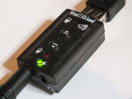
The CM119 IC has, unlike most other sound card controller ICs, no digital highpass inside, which means that it can measure also DC, if the input capacitor is removed. So after modification the device should works on your computer with a bandwidth of DC to 15kHz, which is enough for many purposes of DIY electronics. The capacitor can be pretty easily found on circuit board when you know what you are looking for. On my device that capacitor is market with symbol C6 and one end of the capacitor measures low resistance to the mic input 3.5 mm connector tip.
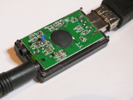
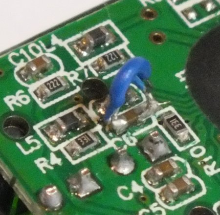
A closer look at my modification. I just soldered a wire that short circuits C6. The SMD components on the circuit board are quite small, so the wire looks quite thick on the picture and it is hard to make a nice looking solder joint. Even if this does not look very good it works well.
I measured that the mic input is by default designed to take around 100 mV AC signal for full output. That’s OK for many uses (use attenuator if you want higher range).
Some modifications and additions needs to be done besides short circuiting C6 to make this USB sound card to be useful DC capable measuring instrument. First the sound card mic input has bias current feed (designed for electret mic powering) that is approximately 4.3V fed through around 4.7 kohm resistor.
The DC potential on the CM119 mic in should be around 2-2.2V DC range for everything to work well. So if I just short circuit capacitor C6, when there is nothing connected to input the voltage CM119 mic in is over the top of the operating range, and when 0V is connected to input it is below lower range.
So what we need is a circuit that would scale the around +-100 mV DC input at around 0V to voltage in around 2-2.2V DC range on soundcard microphone input, preferably with some form of DC bias adjustment.
There are many design for such DC shifting circuits, but many of them need somewhat complicated external powering (dual polarity DC supply usually needed for this kind of opamp circuits). So I decided to make my own.
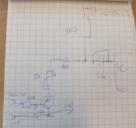
My design consists of one PNP transistor (BC559), one resistor and one potentiometer (10 kohms). Here is my initial design drawing:
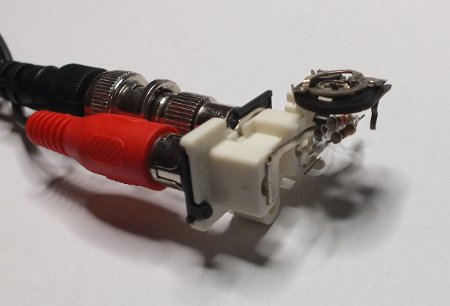
Here is what my initial test prototype looked like. This was designed to be connected between RCA-3.5mm plug cable (red plug) that goes to USB sound card and normal oscilloscope probe (1:1 probe with black BNC connector connected to BNC-RCA adapter).
Here is a clearer schematic of my DC in adapter drawn with Circuitlab (NOTE: I used BC557 transistor but this editor did not know that so I had to substitute it with something that exist on it, closest to that I could find on the included library was 2N3906).
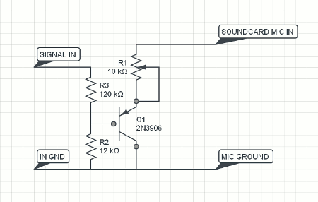
The benefit of this design is that the circuit is very simple and still works well. The downside of this design is that R1 controls both the DC polarity and circuit gain/attenuation. So if you adjust DC with R1 at the same time you change the sensitivity (if you are at normal operation range the change to gain is not very much). Anyways the circuit is simple, cheap, works OK and does not need any external power to operate. The input impedance is around 120 kohms. The circuit accepts signal levels to around two volts as it is. If you want higher input voltage range, you need to add your own external attenuators for that.
Now you have one channel analogue computer interface with a bandwidth from DC to around 15kHz at 16 bit input ADC resolution. This is enough for many purposes of DIY electronics. The “Zeitnitz” tool also adds a two channel signal generator and FFT function!
Great for DIY purposes.
76 Comments
Tomi Engdahl says:
Lissajous Pattern on a Sound Card Oscilloscope & Signal Generator without any Physical Connection
https://www.youtube.com/watch?v=zRFNHtUO2d0
The easiest way to demonstrate Lissajous Pattern in class is to use a sound card oscilloscope and signal generator. The dual-channel signals generated by the sound card signal generator can be fed into the input of the sound card oscilloscope through the loopback established at the sound card mixer level using software configuration without any external physical cable connection. You can do it with just a laptop or tablet PC.
Tomi Engdahl says:
How to Measure a Time Delay Using Cross Correlation?
https://www.youtube.com/watch?v=L6YJqhbsuFY
Tomi Engdahl says:
Soundcard Oscilloscope
https://www.zeitnitz.eu/scope_en
Tomi Engdahl says:
Web based scope
https://www.bellesondes.fr/wavewatch/
It’s a web browser dual channel oscilloscope with a fullscreen, responsive and touch-friendly UI that uses soundcard / mic-in as your input device.
Alternative that did no work for me:
http://www.grauonline.de/alexwww/ardumower/oscilloscope/oscilloscope.html
Tomi Engdahl says:
Virtual Oscilloscope
https://academo.org/demos/virtual-oscilloscope/
This online virtual oscilloscope allows you to visualise live sound input and get to grips with how to adjust the display. If you find this useful, our online spectrum analyser may also be of interest to you.
https://academo.org/demos/spectrum-analyzer/
Tomi Engdahl says:
Schematic Overview
Next
https://makezine.com/projects/sound-card-oscilloscope/
Tomi Engdahl says:
Web Oscilloscope
https://anabrid.dev/webosci/
Tomi Engdahl says:
Webbrowser based oscilloscopes are very handy software Oscilloscopes, because they do not require to install software on the computer. They are also known to run on smartphones and tablets, which makes them quite universal.
What follows is a list of webbased oscilloscopes known to be available.
Simple Demos
https://webaudiodemos.appspot.com/AudioRecorder/index.html
https://academo.org/demos/vectorscope/ (no data aquisition, only output)
https://academo.org/demos/virtual-oscilloscope/ (most sophisticated oscilloscope)
they use this work: https://www.researchgate.net/publication/316744813_Free_oscilloscope_web_app_using_a_computer_mic_built-in_sound_library_or_your_own_files
You can use https://anabrid.dev/webosci/ from any recent web browser.
Tomi Engdahl says:
Web Browser Oscilloscope – Trigger Level Settings #22
https://github.com/ozel/DIY_particle_detector/discussions/22
Tomi Engdahl says:
The frequency range depends on the sound card, but 20-20000Hz should be possible with all modern cards. The low frequency end is limited by the AC coupling of the line-in signal. Be aware, that most microphone inputs are only mono.
Tomi Engdahl says:
Flea-Scope™ USB O-scope (18 Msps, $13 BoM, WebUSB)
Flea-Scope™ is a very low-cost and easy-to-use 18 Msps USB oscilloscope and mixed-signal logic analyzer.
https://hackaday.io/project/192598-flea-scope-usb-o-scope-18-msps-13-bom-webusb
Flea-Scope™ is a very low-cost ($13 BoM in quantity) and easy-to-use 18 million sample-per-second (Msps) USB oscilloscope and mixed-signal logic analyzer with a built-in waveform generator, and so much more, based on the PIC32MK MCU! Flea-Scope can be controlled by any Chromium-based web browser that supports WebUSB API or Web Serial API running on a computer, tablet, or phone (!!!), with no need for further software install – just plug it in and open a web-page and you are up and running!
The Flea-Scope User’s Guide (including some “how it works” internals) is here: https://rtestardi.github.io/usbte/flea-scope.pdf
Tomi Engdahl says:
#413 Your PC Soundcard is an Oscilloscope, a Signal Generator, and a Spectrum Analyzer (Arta, REW)
https://www.youtube.com/watch?v=dX0QkL8xMmE
Oscilloscopes and signal generators are handy tools in our labs. Unfortunately, they are not cheap. What if you had such devices already and did not know?
All newer PCs have loudspeakers and a microphone. So they can create sound as well as record it. And usually in decent quality. Like oscilloscopes and signal generators! We only need a connection and software to create the desired waveforms and visualize the measured voltages. Fortunately, such software is available. And the best: We can use it free of charge!
Tomi Engdahl7 says:
ET601 Five-channels USB-oscilloscope tested
We have never tested a device where the discrepancy between specifications and actual performance is so great. The ET601 is completely unusable as an oscilloscope, but perhaps applications can be found in the field of teaching.
Read this article
https://chinese-electronics-products-tested.blogspot.com/p/et601-five-channels-usb-oscilloscope.html
Tomi Engdahl says:
https://hackaday.io/project/192598-flea-scope-usb-o-scope-18-18-msps-webusb