I bought USB Virtual 7.1 Channel External Sound Card Adapter to build a cheap PC based digital storage oscilloscope. Sound card based oscilloscope is not new to me, I have used it sometimes. There are many free oscilloscope software that you can use. For example “zeitnitz” is a very fine program!
Using an external USB sound card instead of one built onto computer has several benefits: you don’t have to disturb normal PC sound operations with your measurements and mistakes do not break your mains sound card. USB based sound cards are cheap, and some can even be modified a DC measurements capable measuring instrument.
The product I selected for my project is USB Virtual 7.1 Channel External Sound Card Adapter. It is based CM119 USB soundcard IC according to product comments. It seems to be good device, cheap ($3.70) and plug-and-play – easy to use. No extra drivers needed in Windows (should work well on Linux according to comments but I have not tried that myself).
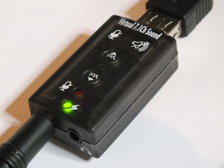
The CM119 IC has, unlike most other sound card controller ICs, no digital highpass inside, which means that it can measure also DC, if the input capacitor is removed. So after modification the device should works on your computer with a bandwidth of DC to 15kHz, which is enough for many purposes of DIY electronics. The capacitor can be pretty easily found on circuit board when you know what you are looking for. On my device that capacitor is market with symbol C6 and one end of the capacitor measures low resistance to the mic input 3.5 mm connector tip.
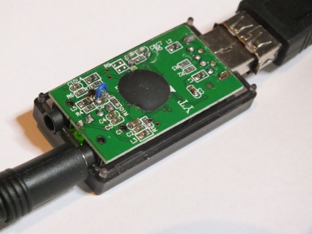
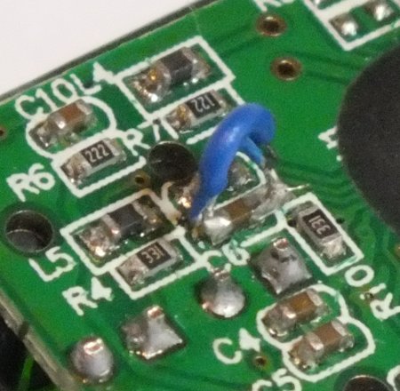
A closer look at my modification. I just soldered a wire that short circuits C6. The SMD components on the circuit board are quite small, so the wire looks quite thick on the picture and it is hard to make a nice looking solder joint. Even if this does not look very good it works well.
I measured that the mic input is by default designed to take around 100 mV AC signal for full output. That’s OK for many uses (use attenuator if you want higher range).
Some modifications and additions needs to be done besides short circuiting C6 to make this USB sound card to be useful DC capable measuring instrument. First the sound card mic input has bias current feed (designed for electret mic powering) that is approximately 4.3V fed through around 4.7 kohm resistor.
The DC potential on the CM119 mic in should be around 2-2.2V DC range for everything to work well. So if I just short circuit capacitor C6, when there is nothing connected to input the voltage CM119 mic in is over the top of the operating range, and when 0V is connected to input it is below lower range.
So what we need is a circuit that would scale the around +-100 mV DC input at around 0V to voltage in around 2-2.2V DC range on soundcard microphone input, preferably with some form of DC bias adjustment.
There are many design for such DC shifting circuits, but many of them need somewhat complicated external powering (dual polarity DC supply usually needed for this kind of opamp circuits). So I decided to make my own.
My design consists of one PNP transistor (BC559), one resistor and one potentiometer (10 kohms). Here is my initial design drawing:
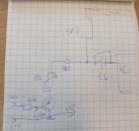
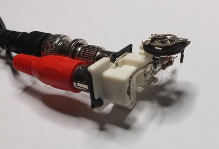
Here is what my initial test prototype looked like. This was designed to be connected between RCA-3.5mm plug cable (red plug) that goes to USB sound card and normal oscilloscope probe (1:1 probe with black BNC connector connected to BNC-RCA adapter).
Here is a clearer schematic of my DC in adapter drawn with Circuitlab (NOTE: I used BC557 transistor but this editor did not know that so I had to substitute it with something that exist on it, closest to that I could find on the included library was 2N3906).
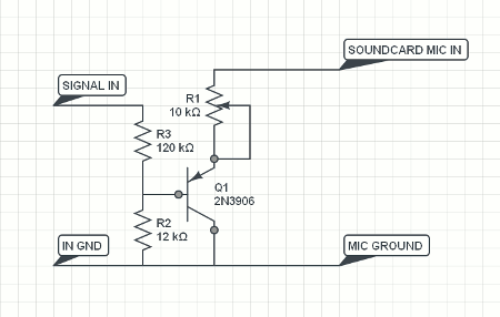
The benefit of this design is that the circuit is very simple and still works well. The downside of this design is that R1 controls both the DC polarity and circuit gain/attenuation. So if you adjust DC with R1 at the same time you change the sensitivity (if you are at normal operation range the change to gain is not very much). Anyways the circuit is simple, cheap, works OK and does not need any external power to operate. The input impedance is around 120 kohms. The circuit accepts signal levels to around two volts as it is. If you want higher input voltage range, you need to add your own external attenuators for that.
Now you have one channel analogue computer interface with a bandwidth from DC to around 15kHz at 16 bit input ADC resolution. This is enough for many purposes of DIY electronics. The “Zeitnitz” tool also adds a two channel signal generator and FFT function!
Great for DIY purposes.
76 Comments
Simon Klein says:
Hi,
I just bought a usb soundcard with the same housing from ebay.com, opened it up and found out that the pcb layout looks quite different. There unfortunately are no pcb-markings, so there is no “C6″. So i measured each capacitor and found that there is one that as you said “measures low resistance to the mic input 3.5 mm connector tip” (in fact its zero resistance). I then soldered a wire-bridge to both ends of that capacitor to short circuit it, opened zelscope and saw just some very low noise around the zero-voltage-line. When i plug in a microphone into the soundcard it doesnt respond to it anymore. Short circuiting both electrodes of the microphone connector leads to a short maximum peak in zelscope. Am i missing something here? I unsoldered the wire bridge afterwards again to set the card into its original state (works as before now).
Regards
tomi says:
When you have done the DC modification for the sound card it does not work anymore with normal mics.
The reason is that the DC potential with mic can vary from mic to mic, and it pretty impropable that the DC potantial with mic falls within the range that the IC input accepts properly.
When you do the DC modification, the soundcard works only with the DC input adapter I showed on the end of the article.
If you want to be able to use both options, you can always solder a switch instead of direct wires. It allows you to select between normal souncard input and DC capable oscilloscope input modes as you need.
Tomi Engdahl says:
Fundamentals of USB Audio
http://www.edn.com/design/consumer/4376143/Fundamentals-of-USB-Audio?cid=Newsletter+-+EDN+on+Consumer+Electronics
In this article we will look into USB Audio: a standard for digital audio used in PCs, smart phones and tablets to interface with audio peripherals such as speakers, microphones, or mixing desks. In this article we set out to show how USB Audio works, what to watch out for, and how to use USB Audio for high-fidelity multi-channel input and output.
USB Audio uses isochronous, interrupt and control transfers. All audio data is transferred over isochronous transfers; interrupt transfers are used to relay information regarding the availability of audio clocks; control transfers are used used to set volume, request sample rates, etc.
Isochronous transfers are used to transfer data in real-time between host and device. When an isochronous endpoint is set up by the host, the host allocates a specific amount of bandwidth to the isochronous endpoint, and it regularly performs an IN- or OUT-transfer on that endpoint.
When using CD rates, such as 44,100 Hz, the transfer rate works out as 44.1 transfers per second. In USB Audio each transfer always carries a whole number of samples; alternating transfers carry 48 and 40 bytes (6 and 5 stereo samples), so that the average rate works out as 44.1 bytes per transfer.
A single isochronous transfer can carry 1024 bytes, and can carry at most 256 samples (at 24/32 bits). This means that a single isochronous endpoint can transfer 42 channels at 48 kHz, or 10 channels at 192 kHz (assuming that High Speed USB is used – Full Speed USB cannot carry more than a single stereo IN and OUT pair at 48 kHz).
When transmitting digital audio, latency is introduced. In the case of High Speed USB this latency is 250 us. A packet of data is transferred once in every 125 us window, but given that it may be sent anytime in this window a 250 us buffer is required. On top of this 250 us delay, extra delay may be incurred in the O/S driver, and in the CODEC. Note that Full Speed USB has a much higher intrinsic latency of 2 ms, as data is only sent once in every 1 ms window.
The big issue in digital audio is to agree on a common notion of time. Above we have defined USB frames to be transferred 8,000 times per second, and set the speakers to play a sample 96,000 times per second. This will only work if the speaker and the host agree on the length of a second. USB Audio offers three modes that ensure that the host and the speaker agree on timings
there are at least two separate clocks in the system, the USB clock with a host driven frequency of 8,000 transfers per second, and a sample clock with an externally driven sample rate of, for example, 96,000 Hz.
These clocks will have subtly different frequencies, and the difference will vary slightly over time. Hence the average number of audio samples per frames will be slightly more or less than the expected rate.
low-level USB stack and the USB Audio stack should be tightly integrated, without buffering in between
Once a device is USB Audio Class compliant, it will integrate neatly into the operating system.
Compliance to the standard makes the device interoperable. O/S vendors can supply a single USB Audio driver that drives a multitude of devices, with a multitude of capabilities.
Indeed, the same USB Audio implementation can be parameterised to implement a different number of channels, and the same driver can be used to interface to the device.
Summary
USB Audio Class 2.0 takes advantage of High Speed USB 2.0, enabling low latency transfer of audio between PC and a connected audio device. The high throughput of High Speed USB 2.0 can be utilised to deliver many audio channels, and with high audio quality. The USB Audio Class standard caters for a wide range of devices, from complex mixing desks with many channels, multiple clock sources and complex controls, to surround sound systems, PC speakers and microphones.
schlesische wurstspezialiäten says:
Definitely, what a fantastic blog and enlightening posts, I definitely will bookmark your blog.Have an awsome day!
Hugh Pattenson says:
Nice site, i have bookmarked it and will be back
Markus R. says:
You use the microphone input, that means it is a 1-channel device?
Is it possible to use the line-in to make it 2-channel?
tomi says:
I use microphone input, which means it is a 1-channel device.
It would be possible to use line-in on USB sound cards that to have 2-channel input.
The none of the USB sound cards I have have line input.
I don’t have plans to modify any line input USb sound card for DC input.
If AC input is enough, then you could use almost any USB sound card with line input as simple oscilloscope.
Tomi Engdahl says:
This web page has instructions to modify one USB sound card line input to DC operation:
Sound Card DC Input Modification
http://www.daqarta.com/dw_ggnn.htm
If you need high frequency response as well as response down to DC, you can modify an existing sound card by adding the DC Input Adapter circuit discussed here. This avoids the input AC-coupling discussed under DC Measurements.
The easiest way to do this is to buy an inexpensive USB card, which can be combined with the DC Input Adapter in an external enclosure, complete with the input connectors of your choice. Alternatively, you can build a compact version of the DC Input Adapter circuit directly into the case of this USB device
grit says:
Looking for setting USB-Audio as default in the Pi’s configuration (for shairtunes) and finally you provided me with the missing step, thanks!
robert says:
It is possible to calibrate this hardware for correct voltage measurment? If so please write simple procedure.thx
tomi says:
Zeitnitz Soundcard Oszilloscope software has some calibration features in it.
There is an offset reset function that can get you rid of DC offset. Just reset when you feed 0V to the input (for example input shorted).
For amplitude calibration you need to have a signal source with a known amplitude (a function generator, oscilloscope calibration signal output etc..).
Then you set the software so that it shows the voltage values right. There is a “Calibration of amplitude” on “Scope parameters” under “Settings” page on Zeitnitz Soundcard Oszilloscope software. Change that parameter so that the display you see on the computer screen matches your signal source.
nch says:
Hi. Please, can you help me with a doubt?
How I could get a DC-coupled output from that usb soundcard?
Many thanks!
tomi says:
I do not have specific tips how to make this specific sound card output DC coupled.
Web page http://www.diyaudio.com/forums/pc-based/224943-sound-card-line-outs-usualy-dc-coupled.html says
“very few will be DC coupled – many audio DAC chip running from 5V have near 1/2 Vsupply offset, are aiming for “desktop consumer” line levels of ~2 Vrms”
So a worth to check option would be what happens if you just short the output capacitors. I expect that you would get a DC coupled signal where zero is near 1/2 of sound card DAC chip operating voltage (I expect that chip operating voltage to be 5V or 3.3V).
nch says:
Thanks Tomi.
I will try what you say.
robert says:
I tried this mod but without c6 (mic cap) i got 2.23V on mic line. Now if signal is above 2.23V i can see waveform, below that not so much, and sensitive band is between 2.08 – 2.34V, minimal gain on windows mixer, standard looking ebay usb card, just like in article.So what could be wrong?
Tomi Engdahl says:
That 2.23V on mic line is what is expected when the capacitor is not there. Also sensitive band is between 2.08 – 2.34 is what the mic input of the IC accepts. Whatever you want to feed in must be in this range (if it is not you need electronics that converts it to this range).
John says:
Just a thought, but wondering if several sound cards can be set up with some of the software packages for several probes.
I still have a bunch I’d like to resource rather than landfill.
Isabell says:
Hi I am so happy I found your weblog, I really found you by mistake, while I
was researching on Digg for something else, Anyways I
am here now and would just like to say thank you for a incredible post and a all round enjoyable blog (I
also love the theme/design), I don’t have time to read
it all at the minute but I have saved it and also
added your RSS feeds, so when I have time I
will be back to read a lot more, Please do keep up the
awesome job.
Tomi Engdahl says:
An Audio Based USB Oscilloscope and Signal Generator for $20
http://hackaday.com/2014/05/27/an-audio-based-usb-oscilloscope-and-signal-generator-for-20/
Are you interested in building a 20kHz 2-channel oscilloscope and a 2-channel signal generator for only $20 with minimal effort? Be sure to check out [Jan_Henrik's] Instructable that goes over how to build this awesome tool from a cheap USB audio card.
Marco says:
I shorted the (a) C6 capacitor as per instructions. Plugged it into my Mac. It was not recognised. After a short period I heard a wee pop. The my computer said it had disabled the USB port due to too high a voltage being detected. I removed the USB Virtual etc etc and smelled it. Shortly thereafter I tossed it in the bin – circuit boards that smell of burning are not usually worth any further time.
What did I do wrong?
Tomi Engdahl says:
Some possibilities:
- unintentional short circuit created when doing modification
- esd spike damaged ic when you did modification
- manufacturer has changed component numbers in new hw revision
Marco says:
Success! After some shenanigans with the quality of the 3.5mm socket n my probe box, I got what looks very close to a square wave displayed on mac, SignalScope. (Synchrocity.wordpress.com).
Thanks.
Marco says:
Thanks Yep – I suspect option 3, as the solder up all went quickly and easily. The components seem more tightly clustered on my device – so option 1 could be an issue. Maybe I’ll try again, hardly a costly component. (:-). Perhaps I’ll actually check that resistance to the 3.5mm tip first this time! (;-(
Juan ramos says:
It’s a very good circuit.. so easy and inexpensive
you can add a little capacitor at the output and a switch in parallel with the cap to change your circuit coupling.. to select AC coupling or DC coupling..
greetings!
arend-paul spijkerman says:
I have these old PCI soundblaster cards laying around, that can be used with soundcard oscilloscope software. I found the 2 decouple capacitors on the line in port. Do you think the trick for the USB device will also work with PCI soundcards ? Short the 2 caps with a little switch, and add a bias circuit.
The card seems to have a small creative ct1297-tat chip for the line in port which of cause has no datasheet on the internet.
Tomi Engdahl says:
The trick used on USB devices to get DC response might or might not work on PCI sound cards.
This depends on sound card design and ICs used in them. Some cards use just DC blocking capacitor,
in some other designs in addition to the capacitor in the input there could be another DC blocking
stage inside the ICs… Different designs exist.
For your specific card I don’t know would it work or not.
Arend-Paul Spijkerman says:
Well .. i think i just tought of a workaround, to be able to more or less measure DC with audio line in port, involving a 4066 quad electronic switch and a parallel port. So use on electronic switch (per channel) to disconnect the signal you want to measure for a temporary from the input, and use another electronic switch to put the voltage of a parallel port line on the input. (of cause the input here is a circuit with voltage divider to the actual input) .. of cause the electronic switches are also controlled by the parallel port. So for 2 channels we need all for 4 4066 switches and 6 parallel port lines. So with this setup we can right just before all the actual measurements very shortly put 0v and 5v on the input, so now the software can be manipulating the parallel port measure what values the input gives for 0v and 5v .. so when it does the actual measurements it should be able to calculate what the actual DC voltage is. So calibrate the inputs, then do say like 1000 readings in x milliSeconds .. then calibrate again. Then measure again for x milliSeconds. Guess i’ll need to make some small changes to my stampdock software to test it, to see if it actually works.
Alex says:
Brilliantly simple – I used this and build myself simple scope. I wanted to ask – for a simple way of extending the range of input signal (say up to 5V DC) would it be enough to increase values of R3 and R2 in your circuit? That 5V range is more useful for measurements of various logic circuits (like TTL).
Tomi Engdahl says:
Change the attenuation formed by R2 and R3 is the key to change the range. Just increasing the value of R3 and decreasing the value of R2 will reduce the sensitivity.
If you replace R3 120 kohm resistor with 1.2 Mohm resistor, the attenuation will be 10 times more.
“The circuit accepts signal levels to around two volts as it is”, so after modification the it would accept signals to around 20 volts.
If you select R3 value of something like 470 kohms, I expect you get pretty useful range of around 7-8 volts or so…
Frank says:
Hi,
I recently bought a USB sound card that looks similar to the one you have. But, instead of a cm119 it has a cm108 on board. I checked the data sheets of these chips and they look pretty much the same. On the cmedia site the cm119 looks optimized for VoIP.The board is different too. I checked the cap with the lowest resistance and that one is called ‘C3′. It is partly under the plastic blob covering the cm108.
I wander if this one can be used for the scope using the short you suggested for measuring DC.
cheers,
Frank
Tomi Engdahl says:
You are right that on the data sheets those two chips look pretty similar
http://www.repeater-builder.com/voip/pdf/cm119-datasheet.pdf
http://www.halicky.sk/om3cph/sb/CM108_DataSheet_v1.6.pdf
I have not tested suitability of cm108 so I can’t say anything for sure, but I would think it could be wort to test – the risk of breaking one very cheap sound card might not be that big – and it could work.
If you go this route, I would like to know how this project went – share here so other people can enjoy it as well.
Tomi Engdahl says:
One Dollar USB Sound Card Turned O-Scope
http://hackaday.com/2015/11/04/one-dollar-usb-sound-card-turned-o-scope/
Using the inputs on a computer’s sound card is an old trick to fake a very simplistic, AC coupled, slow oscilloscope. You can get DC operation by desoldering a couple capacitors, but if the sound card is integrated into the motherboard it raises the stakes if you mess that up.
[TMSZ] has a better option, a ~1 dollar USB sound card which is easily hacked to work as a simple oscilloscope.
Software and DLL files to use the sound card with Miniscope v4 — a Windows GUI for oscilloscopes — are also linked, so getting set up should be fairly simple.
Now of course this is not lab-grade measurement equipment: the sampling rate is limited to 44KHz and the voltages must be in the typical “line level” range, under two volts. If you don’t mind a little extra noise, you can increase the input impedance with a single resistor.
Cheap C-Media (?) sound card
http://tomeko.net/dsoundscope/C_Media2/
This USB sound card that presents itself as C-Media is one of the cheapest sound cards available with price $1.1-$2 depending on vendor.
Miniscope v4
http://tomeko.net/miniscope_v4/
Tomi Engdahl says:
A Tale of Two (Sub $100) Oscilloscopes
http://hackaday.com/2016/01/27/a-tale-of-two-sub-100-oscilloscopes/
if you are trying to corral electrons into doing useful things, a scope is a necessity. You can’t visualize what’s happening in a circuit any better than using an oscilloscope. Historically, the devices were expensive and bulky.
These days, scopes are relatively cheap, depending on what you have in mind for performance. They are also highly portable, which is nice. I
That’s how I came into possession of two cheap scopes I wanted to talk about. They are similar in ways but different in others. Neither are going to replace a real bench scope, but if you want something portable, or you are budget-limited, they might be worth a look.
Cheap Scopes
Before I dive into any details, you might think about how much you are willing to spend for a scope–especially if it is going to be your only one. If you are just looking to save money, my opinion is that you are better off buying a cheaper, older bench scope. With the availability of perfectly good scopes from Owon, Rigol, and others in the $300 range means older scopes can only sell for so much. Granted, if you actually need a scope with 5 GHz bandwidth, you are still going to have to spend a lot of money, but for most of us, a 50 or 100 MHz scope with a few channels is perfectly fine.
There is a rash of very cheap scopes based on fast ARM or other processors. These are neat, but the reality is that many have low-bandwidth front ends or suffer from other issues. Some of the $15 or $20 kits are reasonable at that price, but once you get up to the $100 neighborhood, I think you should have better if you are looking for your first scope. The same goes for “soundcard” scopes (mainly an input network that feeds signals into your PC’s soundcard). Fine for a DIY project, but probably not what you want for your only scope.
The two scopes I want to look at for now are the Owon Wave Rambler and the AllSun (or, sometimes, ESun) EM125. The Owon is a small hand-held probe with a USB cable that sends data back to a PC application. The EM125 is a scope meter — it has a small display and can also work as a volt or ohm meter. It does not connect to a PC. Either instrument costs just about $100 and is easily available.
The EM125 is about the size of a mid-size digital volt meter, but while most volt meters are held in a portrait orientation, the EM125 is landscape
The scope part of the instrument has a reported 25 MHz bandwidth and there is a proper connection for a scope probe. The meter section uses a standard shielded banana plug.
I don’t like to use a scope’s auto function, but on this little meter, it is handy just to hold down the button and let it find proper settings for a given waveform.
The Rambler is not too different from the EM125 regarding cost or performance. It also claims a 25 Mhz bandwidth. It is USB powered
You must use the Windows software to see any results
There is some very basic open source for the OWON RDS scopes
How Do They Work?
Subjectively, both of these devices feel different from using a normal oscilloscope.
Honestly, I might use the Rambler more if it supported Linux nicely. It is much more like an ordinary scope in function, if you can just get used to the feel of it and don’t mind lugging a PC around.
Raghu says:
Can use this circuit http://xoscope.sourceforge.net/hardware/hardware.html for the sound card u used after shorting the capacitor ?
Tomi Engdahl says:
I think that circuit from http://xoscope.sourceforge.net/hardware/hardware.html could work without problems (although I have not tested) if connected to my DC input circuit (that one with transistor in it).
Raghu says:
Should I keep a switch and use both the circuits, where one is used in measuring DC and the other for AC.
Thank you
Tomi Engdahl says:
Potentially suitable for similar modification
http://www.banggood.com/3Pcs-Free-Drive-USB-Sound-Card-Notebook-Computer-External-Sound-Card-Module-USB-p-1107812.html?rmmds=newArrivals
Tomi Engdahl says:
Soundcard DC in/out
http://www.daqarta.com/dw_ggnn.htm
http://www.daqarta.com/dw_ggmm.htm
Tomi Engdahl says:
Line out bias on sound card output
https://electronics.stackexchange.com/questions/104101/line-out-bias-on-sound-card-output
I recently bought an USB sound card to do some measurements/experiments with.
Interestingly the ground of the female audio jack is not connected to the USB ground, it is DC biased with about 1.67 volts with respect to USB GND (half the AVDD supply voltage).
the USB sound card uses the VT1620A chipset – datasheet:
http://www.cqham.ru/forum/attachment.php?attachmentid=113311&d=1338984800
I would assume it’s applying that DC-bias because it is cheaper to use an amplifier to generate a mid-rail then use proper series-capacitors to decouple the line out signals.
Basically, the line outputs need to be able to swing positive and negative. The general way this is done is with a series capacitor in each line-out connection, which blocks the DC. However, to get low enough frequency response with headphones, which can be as low as 8Ω, you need a very large capacitor, which is expensive/physically-large.
Tomi Engdahl says:
http://www.diyaudio.com/forums/pc-based/224943-sound-card-line-outs-usualy-dc-coupled.html
I have a sound card that is DC coupled. I’m trying to think of the name of it but my back is out and I cannot go looking on the shelf. It is an ISA bus card however and I don’t have any motherboards in service that have ISA slots.
Edit: It was *not* cheap.
very few will be DC coupled – many audio DAC chip running from 5V have near 1/2 Vsupply offset, are aiming for “desktop consumer” line levels of ~2 Vrms
more DAP today are DC coupled – still not universal – DC coupled outputs with sw C inveter/splitters or actrive gnd are built into some of these low V portable audio DAC chips to save the size of the output C and because they are used with low Z, sensitive headpnones that are loud with < 1 Vrms drive
some DAQ are fairly low cost ~$200 gets 12 bits analog I/O with industrial specs, DC response
Tomi Engdahl says:
How to fix cheap USB sound card
https://www.youtube.com/watch?v=4GNRzwfP7RE
Some cheap (1GBP or $1) USB sound card are missing the needed coupling capacitors in the headphone output. That can break headphones and the sound card due the constant power draw caused by huge DC offset voltage. Leaving those capacitors out will cut the cost little bit, but it will have dramatic efffect on sound quality and reliability of the sound card. For some reason manufacturer left those capacitors out and replaced them with traces, that way both AC and DC can go from the IC inside the epoxy blob to the headphone jack.
Tomi Engdahl says:
USB 3D sound card fix
http://leeds49.co.uk/2013/12/13/usb-3d-sound-card-fix/
I plugged one in and it was running in seconds, the first thing I noticed was how bad it sounded then my earphones got hot.
I looked at the voltage output on the left and right channel and saw just over 2v DC on both.
Tomi Engdahl says:
CheapChop: measuring DC with a sound card
http://lea.hamradio.si/~s57uuu/scdsp/CheapChop/cheapchop.htm
It uses a single 74HC4066 chip containing four CMOS switches, and a few resistors and capacitors. The components in the above schematic will cost about a couple of Euros, but you will probably want to spend a little more for a small box and some connectors.
Two of the CMOS switches make up an astable multivibrator, that oscillates at cca 5kHz. Their outputs control the remaining two CMOS switches, that chop two DC voltages for the two sound card channels.
I’ve made the circuit fully symmetrical, to reduce crosstalks. The two chopping switches are operated anti phase, and could be connected as a SPDT switch, if needed.
Tomi Engdahl says:
One Dollar USB Sound Card Turned O-Scope
https://hackaday.com/2015/11/04/one-dollar-usb-sound-card-turned-o-scope/
Using the inputs on a computer’s sound card is an old trick to fake a very simplistic, AC coupled, slow oscilloscope. You can get DC operation by desoldering a couple capacitors, but if the sound card is integrated into the motherboard it raises the stakes if you mess that up.
[TMSZ] has a better option, a ~1 dollar USB sound card which is easily hacked to work as a simple oscilloscope. Easily found on eBay, the 7.1 virtual channel sound card
Cheap C-Media (?) sound card
http://tomeko.net/dsoundscope/C_Media2/
This USB sound card that presents itself as C-Media is one of the cheapest sound cards available with price $1.1-$2 depending on vendor.
Tomi Engdahl says:
You Can Make an Oscilloscope Out of a Cheap USB Sound Card
Follow this tutorial to turn a USB sound card into an oscilloscope that can be used with your computer.
https://www.hackster.io/news/you-can-make-an-oscilloscope-out-of-a-cheap-usb-sound-card-cf3d424d7dd8
Analog Front End for Oscilloscope
https://www.instructables.com/id/Analog-Front-End-for-Oscilloscope/
Tomi Engdahl says:
You Can Make an Oscilloscope Out of a Cheap USB Sound Card
Follow this tutorial to turn a USB sound card into an oscilloscope that can be used with your computer.
https://www.hackster.io/news/you-can-make-an-oscilloscope-out-of-a-cheap-usb-sound-card-cf3d424d7dd8
Tomi Engdahl says:
Use your PC Soundcard as an Oscilloscope, a Signal Generator, and a Spectrum Analyzer (Arta, REW)
https://www.youtube.com/watch?v=dX0QkL8xMmE
Oscilloscopes and signal generators are handy tools in our labs. Unfortunately, they are not cheap. What if you had such devices already and did not know?
All newer PCs have loudspeakers and a microphone. So they can create sound as well as record it. And usually in decent quality. Like oscilloscopes and signal generators! We only need a connection and software to create the desired waveforms and visualize the measured voltages. Fortunately, such software is available. And the best: We can use it free of charge!
REW Software: https://www.roomeqwizard.com/
Arta Software: https://artalabs.hr/
Tomi Engdahl says:
Use your PC Soundcard as an Oscilloscope, a Signal Generator, and a Spectrum Analyzer (Arta, REW)
https://www.youtube.com/watch?v=dX0QkL8xMmE
Oscilloscopes and signal generators are handy tools in our labs. Unfortunately, they are not cheap. What if you had such devices already and did not know?
All newer PCs have loudspeakers and a microphone. So they can create sound as well as record it. And usually in decent quality. Like oscilloscopes and signal generators! We only need a connection and software to create the desired waveforms and visualize the measured voltages. Fortunately, such software is available. And the best: We can use it free of charge!
Tomi Engdahl says:
Input buffer and attenuator for sound card oscilloscopes extends low-end frequency response
https://www.edn.com/input-buffer-and-attenuator-for-sound-card-oscilloscopes-extends-low-end-frequency-response/
Tomi Engdahl says:
$3 Homemade Oscilloscope for Smartphones and Tablets.
https://www.youtube.com/watch?v=okP4a6NrhlQ
A simple homemade oscilloscope that we will need later when designing our important project. This unit is fairly easy to make just follow the diagram. Keep in mind that the max voltage your phone could handle is 3.7 volts and your wave is about 20mV. The software I am using is called AR-Oscilloscope.
Tomi Engdahl says:
https://www.eevblog.com/forum/projects/realtime-fft-for-0-30khz-best-bang-for-the-buck/
https://www.daqarta.com/
Tomi Engdahl says:
IMPROVED AUDIO SPECTRUM ANALYZER
WITH THE SOUNDCARD
https://www.qsl.net/pa2ohh/12audiosa.htm
Tomi Engdahl says:
Sound Scanner and FFT Analyzer
https://www.codeproject.com/Articles/58148/Sound-Scanner-and-FFT-Analyzer
Tomi Engdahl says:
https://www.virtins.com/multi-instrument-spectrum-analyzer.shtml
Tomi Engdahl says:
#413 Your PC Soundcard is an Oscilloscope, a Signal Generator, and a Spectrum Analyzer (Arta, REW)
https://www.youtube.com/watch?v=dX0QkL8xMmE
Oscilloscopes and signal generators are handy tools in our labs. Unfortunately, they are not cheap. What if you had such devices already and did not know?
All newer PCs have loudspeakers and a microphone. So they can create sound as well as record it. And usually in decent quality. Like oscilloscopes and signal generators! We only need a connection and software to create the desired waveforms and visualize the measured voltages. Fortunately, such software is available.
Tomi Engdahl says:
Using a PC sound card to receive VLF radio signals
https://www.youtube.com/watch?v=L2W1x6Rb9hI
Just connect an antenna to your computer’s microphone input, and you can receive VLF (Very Low Frequency) radio signals! A sound card (or built-in sound chip) with a recording sampling rate of at least 96 kHz is recommended.
Tomi Engdahl says:
Weekend Projects – Sound Card Oscilloscope
https://www.youtube.com/watch?v=5s-zocXvk2I
https://makezine.com/projects/sound-card-oscilloscope/
Tomi Engdahl says:
DIY ECG with AD8232 and Sound Card
https://www.youtube.com/watch?v=sP_-f5nsOEo
This DIY ECG uses an AD8232 breakout board sending the ECG signal through the microphone jack of my computer sound card. Custom software (free and open source, written in C#) graphs the signal in real time and displays heart rate over time.
Tomi Engdahl says:
Soundcard oscilloscope review
https://www.youtube.com/watch?v=9N-MyEX7Yt4
Soundcard oscilloscope is a very well written LabView application. It is available for free as long as it is used non-commercially.
Tomi Engdahl says:
Digital Signal Generator for Sound Cards (made in Visual Basic 6.0)
https://www.youtube.com/watch?v=OJp-w6ObREA
Tomi Engdahl says:
Free Waveform Generator
https://www.youtube.com/watch?v=pfGsljl9O5A
Tomi Engdahl says:
Audio Signal Generator in Python
https://www.youtube.com/watch?v=Kowm5IUPeyU