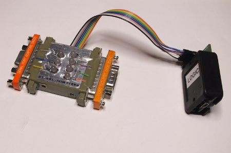
RS-232 serial interface is still quite widely used in many applications. Usually RS-232 Mini Tester with LEDs for indicating state of different signals is all that is needed to make things work. But sometimes seeing signals with your eyes is not enough for troubleshooting and testing.
There are nowadays cheap logic analyzers (like Saleae Logic and USBEE) that can easily record many channels of fast changing digital signals and even decode the serial data on the line. Those would be ideal tools for serious debugging of RS-232 signals. But those devices have one downside: they are designed only for TTL (5V) and LV-TTL (3.3V) level logic signals. Standard RS-232 signal levels (typically +3..15V and -3..15V, but can be up to +-25V) are too much for those logic analyzers. Connecting logic analyzer directly to RS-232 signal will most probably damage the hardware. So I need some form of converter that can convert RS-232 signals to TTL signals.
One option would be to use several MC1489 Quadruple Line Receiver or MAX232 ICs to do the conversion. The downside is that this need power to operate. Another option that comes to my mind is to use zener diode voltage limiting circuit (resistor and zener diode). I tried that but with the zener diodes the first trials did not give well working implementation.
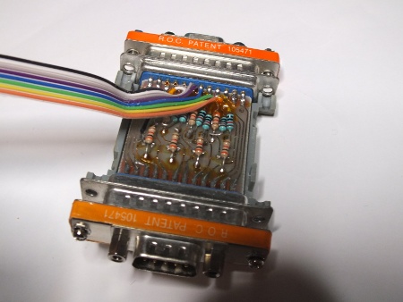
Then I ended up a really simple implementation that seemed to be “good enough”: I found out that just putting a 10 kohm resistor between the RS-232 signal and logic analyzer input was enough. The HC245 IC used on the input has built-in protection diodes on the inputs and that 10 kohm resistor limits the current to safe level for them (at maximum RS-232 signal level the current would be around 2 mA). This was a simple and well working approach.
I ended up building my circuit inside a RS-232 Mini Tester I had lying around. This construction gave me nice boxed device that works as an useful debugging too with and without connection to logic analyzer. I taped wire pieces next to each LED on the RS-232 Mini Tester to be instructions how to connect the adapter to logic analyzer (which wire carries which signal).

The following picture shows how I soldered 10 kohm series resistor from RS-232 line to logic analyzer input wires inside the RS-232 Mini Tester.

4 Comments
Tomi Engdahl says:
Another idea for debugging RS-232 signals is shown in this web page:
Serial port logic analyzer
http://www.consistent.org/serial-la/
The serial-la suite are a set of programs designed to use the four
status lines on a serial port as a sort of “logic analyzer”. Programs
are also provided to decode the data as RS232 of an unknown nature
(assuming you’ve connected the data pin to one of the status pins).
lasample is the program which actually reads data from the serial port
and writes it to a file.
lachart produces a text bar chart of the signals.
In some sense the flagship of the LA suite, lars232 determines timing,
word size, and parity information for any RS232 data which is recorded
using one of the status pins on the port. This allows for rapid and
fairly reliable determination of the parameters of an unknown signal,
without resorting to trial-and-error methods.
Jones sabo and maybe even platinum eagle says:
Simply wanna input on few general things, The website design is perfect, the written content is rattling wonderful : D.
Jaden says:
Which type of zener diode we must use in zener diode voltage regulator
Yonyr says:
I hope this could also work with eagle pcb price