Traditionally analogue video transmission is done using 75 ohm coaxial cables. Those video signals are not directly compatible with nowadays more widely used twisted pair wiring (CAT5, CAT6 etc..), which means you just can’t wire the signals directly form video output to a twisted pair wire. The mains problems in connecting 75 ohms video source to twisted pair wiring are wrong impedance (75 ohms vs 100 ohms) and wring type of interface (UTP noise rejection will not work if one wire carries signal and other is ground). Whereas co-ax cables are classed as an “unbalanced” mode of transmission, CAT5 twisted pair is known as a balanced mode.
The secret to sending signals over UTP is to balance them well in order to limit both radiation and noise pick up. In this balanced mode, the two cores carrying the video signal are balanced to a particular reference point and the cable twists enable a uniform rejection of the interference, effectively cancelling it out. To produce a balanced signal BALUNs are used, standing for BALanced to UNbalanced. For at least 20 years products have been available capable of transmitting video using UTP wire. There are nowadays many adapters (video baluns) that make this possible. Sending AV over CAT5 is an ecellent alternative to using regular coaxial cable; you can run the signal longer and the cable is cheaper, but the baluns also cost some money. Most use of CAT5 cable in CCTV installations involves using equipment called baluns, however it is possible to use CAT5 without a balun on short cable runs although using a balun will always produce superior results.
Video signal can be adapted to UTP wiring using a special balun between BNC video connector and the wisted pair wiring. There are both passive solutions (balun transformers) and active converters available on the market for this application. Passive baluns require no power to operate and work up to distances of about 500 meters. Active baluns require power for their “active” circuitry and can send video signals over 1Km down low-cost CAT5 cable.
The attenuation characteristics of the UTP are an order above those of coaxial cable. Here is some data on loss in dB per 100ft (~30m) of common cable types:
Freq.(MHz)  RG59  RG6  CAT-5
     1       0.4   0.2   1.8
    10       1.4   0.6   5.8
    50       3.3   1.4  11.0
   100       4.9   2.0  19.3
   200       7.3   2.8  29.3
   400      11.2   4.3  42.0
I will discuss in this article how those passive baluns work. Video balun transformer converts the unbalanced video signal to balanced signal which nicely travels through the cable. Similar transformer can be used on the other end of the cable to convert the video signal back to unbalanced format which fits to BNC connector. Baluns contain small signal transformers that are specially tuned to match the cables impedance and convert the unbalanced signal to a balanced one. Passive baluns just have the transformers and very little else in them.
Simple UTP baluns just convert an unbalanced coax signal to a balanced signal for use on the twisted pair, better baluns also do good impedance matching. If you wish to use UTP for analog video, be sure you get performance data on the baluns that show the entire operating range. When transmitting audio and video signals through twisted pair wiring, use the adapters from the same manufacturer on the both ends of the cable, because those baluns are not standardized.
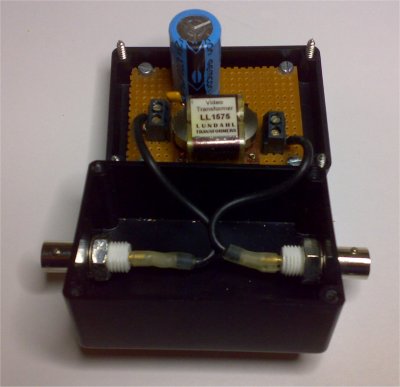
So what is inside those baluns? Let’s start with the most obvious solution: isolation transformer. Build video isolator shows a construction of video isolator transformer:
This same circuit would work as video balun when you wire the output to twisted pair instead of coaxial output. The good sides of this design is very good balance and immunity to ground loop noise (complete transformer isolation from input to output). The downsides of this kind design are that this design does not provide impedance matching, this design does not pass DC and the transformer I used is quite expensive component. The impedance mismatch 75-to-100-ohms gives calculated return loss of 16.9 dB, which is quite acceptable, especially to situations where the baluns are situated next to the equipment on both ends. It would be possible to do impedance matching if you can find 75 ohms to 100 ohms video isolation transformer and use it instead of 1:1 video isolation transformer.
The blocking of DC can be a problem. Broadcast-quality video typically requires performance all the way down to DC. Since a traditional transformer cannot pass DC, other methods are used to design these baluns, and the most often used design is current mode balun. A current balun allows working currents to pass but chokes common mode currents – nothing more: a current balun controls currents presenting a low impedance, through the device, to desired currents but a high impedance to unwanted ones.
If you want to pass DC, you need to use current mode balun. It will easily pass DC and do the balancing quite well. The following picture from A Cost Effective Current-mode 1:1 Balun article shows the basic idea how this kind of balun is built.
The operating principle is that the inner conductor and the inside of the braid act as two opposing bifilar windings with substantial inductance inserted in the outside of the braid. Differential current passes through such a transformer with little insertion loss as the opposing windings of the transformer mode effectively eliminate the winding inductance. The same principle applies in the common-mode choke where two or more wires pass through a ferrite core. For video applications you can see some details of possible construction for video current mode balun at my Build humbugging transformer, although for this application the design could be optimized (can be built using much smaller core).
This design will pass DC nicely and will do balancing. This design does not offer any impedance matching. The impedance mismatch 75-to-100-ohms gives calculated return loss of 16.9 dB, which is quite acceptable, especially to situations where the baluns are situated next to the equipment on both ends. I have successfully built current mode baluns and used them successfully to send video though UTP cable. When the adapter have been very near to equipment on the end the video quality has been pretty acceptable (if you have long coaxial cables between equipment and balun, I get easily ghosting).
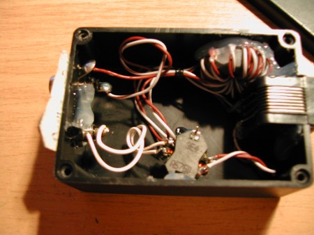
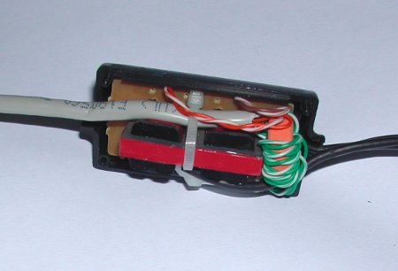
There are pictures of two audio + video baluns I have built using my own current mode balun design and audio isolation transformers:

The current mode balun transformers were just built on toroidal high permiability toroidal cores. The wire I used was wiring was one wire pair from CAT5e cable. The video balun in picture above is 22 turns of one wire pair from CAT5 UTP cable over RIK 20 ferrite core. RIK 20 characteristics: dia.21.2xdia.8.7×8.2mm, N30, Al=4100nH/1t. With this core and 22 turns, the inductance for common mode signal will be around 2 mH (inductance for differential signal will be pretty close to zero).
The picture below shows another balun I built. The audio transformers and case are from audio isolator sold years ago by Biltema (Biltema 31441 GALVAANINEN RCA-EROTIN ). The toroidal core used in this designs had pretty similar characteristics but made by some other company (I do not have record on the manufacturer or exact type number anymore). On the second balun the inductance for common mode signal was around 2 mH.

Professionally video baluns typically combine the current mode balun design with some form of impedance matching circuitry (typically special transformer + resistors + capacitor design that passes DC nicely but provides impedance matching to high frequencies where it is most needed). Nowadays there are many cheap video baluns available, so it not usually economically feasible to build your own video baluns.


4 Comments
VGA over UTP « Tomi Engdahl’s ePanorama blog says:
[...] over UTP I have written about sending video signals over UTP cable. I have covered single composite video signal and audio. Now it is time to discuss sending VGA over [...]
Ali Habibi says:
Hi
Passive balun act as the filter,if you design it for mid frequency (if we consider video spectrum from 20 to 2M) then some
part of video signal become attenuated,it means picture is not sharp and clear as input ,for good result it is better to use
coax cable….
Tomi Engdahl says:
Balun can cause some attenuation to signal, depends on the balun design and quality.
But it is not nowadays always better to use coax. For example typical high quality baluns connected to CAT5/CAT6 UTP can outperform coax on longer runs on signal details compared to cheap RG59 coax. Good UTP + balun can provide lower high frequency attenuation and be less susceptible to many noise sources for example for composite video signal.
It depends on the video signal type and coaxial cable properties when coax or UTP would perform better.
There is place for both coax and UTP solutions in video systems.
Tomi Engdahl says:
“Anyone have any experience with transmitting analogue or digital audio over Cat cable (with the caveat of it still sounding good at the other end).”
Yes. If your devices have balanced interfaces, then it will run quite nicely
https://www.epanorama.net/blog/2021/04/17/xlr-over-cat-567/
If interfaces are unbalanced then you need audio balun on both ends. Audio isolation transformers work quite ok for this as passive circuit.
For digital SPDIF signal video baluns will usually work OK.
“▶️Interfacing with cat6 – it’s just a 100Ohm Transmission line, right? I’m guessing if I want isolation, Ethernet transformers won’t work?)”
Ethernet transformers work well only for signals at frequency range used for Ethernet, typically starts from 100 kHz and goes up to 10-100 MHz or more.
For analog audio you want audio transformers that can handle audio frequencies. 600:600 ohm transformers work OK.