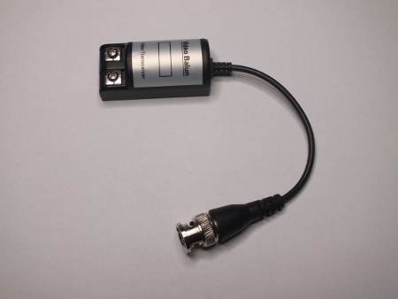
The secret to sending analogue video signals over UTP is to balance them well. Video balun is a device made for this. I earlier write about Video over UTP and my own experiments related to it. Here is a look wat what is inside a commercially made inexpensive video balun, in this case LLT-201 from Dealextreme. That video balun works pretty well for carrying composite video over CAT5, CAT5e or CAT6 UTP cable (and also works on older telephone wiring on short distances).
Here is LLT-201 video balun tear-down:
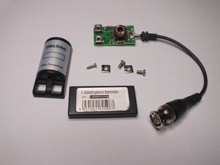
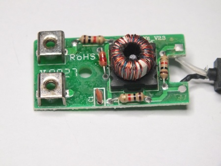
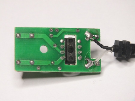
Ad you can see inside the device there are just one special transformer, few resistors, one capacitor and one semiconductor that looks like diode (I quess that it some type of over-voltage protection component). The transformer is would on toroidal core and has three windings that look like to have same number of turns in then. To get idea of the transformer I also measured the inductance of one coil with my RLC meter and got reading 14 mH.
I looked at the circuit board and I draw a circuit diagram of the device based on that:
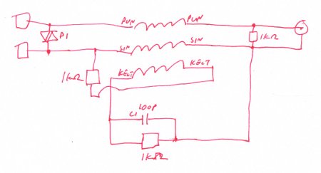
Video Balun circuit
The two upper coils seem to form a current balun / common mode construction like what I described on my Video over UTP. The special thing seems to be on the third coil and the components connected to it.
I think that they could in some way tape part in some form of impedance conversion circuit (75 ohms to 100 ohms), but I am not completely sure of that. I tried to measure the impedance on the both sides of the circuit, but I did not see any significant impedance conversion: When there was 75 ohms on the BNC side, the twisted pair side was still closer to 75 ohms than 100 ohms. Anyway the balancing act seemed to work well.
16 Comments
Visit Link says:
Heya i will be somebody in charge of the following. I came across this kind of board i in locating It genuinely beneficial & this helped me to away significantly. I hope to offer some thing once again and enable some others that you served my family.
Tomi Engdahl says:
PV840XFMR PDF
Video Balun
http://www.etslan.com/products.cgi?cat=6
http://www.etslan.com/download.pl?typ=prod&file=374.pdf&name=PV840XFMR.pdf
The ETS Video Balun converts an unbalanced baseband signal to a balanced signal in order to run over structured UTP cabling. The Video Balun requires a pair of balancing resistors. (Note the ETS Special user diagram).
The ETS Video Balun grants the freedom to use UTP instead of costly coax to transmit baseband video signals throughout a facility, with better signal characteristics and lower cost. Depending upon the application, installers may be able to utilize previously installed wiring, with a corresponding dramatic improvement in cost of installation.
Tomi Engdahl says:
https://muxlab.com/wp-content/uploads/2012/10/CCTV-Balun-Application-Guide.pdf
The purpose of this document is to explain how to apply the CCTV Balun under differentoperating conditions and to discuss issues that are not necessarily covered in the productDatasheet or Installation Guide
The function of the CCTV Balun is to allow the traditional 75-ohm coaxial video cable tobe replaced by Category 5E/6 (or better) twisted pair in the CCTV security andsurveillance environment, thereby allowing CCTV camera and monitoring equipment tobe deployed more cost-effectively using structured cabling techniques.
Picture Problems
During the installation of the CCTV Balun various picture problems may result. It is important to know what is causing these problems and how to correct them.
Total Absence of Signal
This problem is almost always due a discontinuity in the connection between the cameraand the mux. Check the continuity of the twisted pair link.
Presence of Signal But No Image
This problem is most likely due to a reversal of the polarity of the wires between the twoCCTV Baluns at either end. The CCTV Balun is reverse polarity sensitive.
Smearing
Smearing occurs when the edge of an image leaves trail traces similar to smudging a lineof ink on a piece of paper. This may occur as the length of twisted pair cable increases.
Flutter
Flutter occurs when the background fluctuates between light and dark. This symptommay be due to problems with the grounding between the CCTV equipment or the connection may be picking up some external interference from a nearby power transformer. A solution to minimize this effect is to adjust the monitor’s contrast and brightness
Ghosting
Ghosting is characterized by a second video image being received after the main image,resulting in a double image that is skewed in relation to the first. This is usually due to aproblem with the UTP cable connection itself. Poor crimping, untwisted pairs, some of the twisted pairs may be longer than others, poor quality cable, exceptionally high crosstalk between the camera and the monitor are all some of the causes. In these cases it is best to replace the existing cable with a new one.
Loss of Color and Image Detail
Loss of color or image detail may occur if twisted pair cable length exceeds the distance specifications. As the maximum distance specification is neared, the physical properties of the cable and baluns will begin to show this effect. This is due to the effects of propagation delay and attenuation. Other than using an active device, one can improvethe image by shortening the length of twisted pair or by eliminating other contributing signal losses such as splices, cross-connects, low-grade patch cables, etc. The CCTV Balun is specified to support color composite video up to 2200 ft via Cat 5 cable. Whenthe cable distance is exceeded the first effect on picture is loss of color.
Cabling Guidelines – External EMI and RFI
The installation of the CCTV Balun should follow the cabling guidelines outlined in theTIA-568 standard for structured cabling. In regard to external EMI and RFI, it is recommended to keep the CCTV cabling away from strong sources of radio frequency orelectromagnetic radiation:
a) 5″ from power lines of 2 kVA or less.
b) 12″ from fluorescent lighting & power lines between 2 & 5 kVA.
c) 36″ from power lines greater than 5 kVA.
d) 40″ from transformers & motors.
Flat untwisted cable is not recommended
Ground Loop Problems
Due to the fact that the CCTV Balun features DC-continuity, one must be careful about ground loop problems. If there is a serious ground loop problem, then higher than normal current may flow between the CCTV camera and mux. This could cause the coil inside the CCTV Balun to overheat and fail. This problem can be spotted by the appearance of a pin-hole burn in the side of the balun. The balun will no longer operate after this
One remedy is to correct the ground loop problem or replace the cable by coax, although the ground loop problem will continue to exist. Another solution is to install a ground-loop blocker on the line.
Transmitting 24VAC and/or Audio In The Same Cable
24VAC and/or audio may be passed on separate twisted pairs under the same Cat 5 cable jacket as the CCTV video signal without affecting picture quality. In regard to transmitting 24VAC over adjacent twisted pairs, the voltage level will drop in strength as the cable length increases.
Measuring Effective Cable Length
The maximum distance supported by the CCTV Balun is 2,200 feet in a point-to-point connection. Based on a typical DC loop resistance of 19.2 Ω/100m (58.5 Ω/1000ft), thistranslates into a DC loop resistance of 128 Ω. To determine whether the link is within specification, short the twisted pair at one end of the link and measure the DC loop resistance with an ohmmeter.
Extending Distance via Parallel Twisted Pairs
The CCTV Balun is specified to support up to 2200 feet in color via a single Cat 5twisted pair. If the distance required exceeds 2200 feet, it is possible to extend the distance further by paralleling additional twisted pairs, provided spare pairs are available and provided the additional pairs are the same length as the original pair.
The effect of this is to lower the overall signal loss due to the cable. In order to avoid image ghosting, it is important to make sure that all twisted pairs that are paralleled are exactly the same length.
Cable on the Reel
Frequently it may be necessary to pre-test a CCTV Balun installation with some spare twisted pair cable. It is important to note that when the cable is on the reel, the picture will be inferior. This is due to the increased magnetic induction created by the spool of cable. In order to properly pre-test a configuration, it is recommended to un-coil the cable and lay it out flat on the floor or in a cable farm structure.
Cabling Splicing Techniques
When connecting more than one segment of twisted pair cable together to achieve alonger distance it is important to ensure straight-through polarity and that the wires are not crossed. Furthermore, when the wires are spliced back it is important to maintain the twists as close to the connection point as possible. Not more than 0.5” should be untwisted.
In terms of insertion loss, the effective loss of distance due to the splice is negligent. As a rule of thumb one could assume an effective distance loss of 10 to 15 feet for calculation purposes.
Multiple CCTV Signals Under One Cable Jacket
Multiple CCTV camera signals may be transmitted under a single Category 5E/6 cablejacket. As long as the cable is rated Category 5E/6 or better, the number of pairs may be4, 25, 50, 100 or 200 pairs). The rating of Category 5E/6 ensures that performance is adequate enough to prevent CCTV signals from interfering with each other under the same cable jacket. To locate sources for multipair Cat 5 cable, please contact your local cable and connector vendor.
Cable Types Supported
The CCTV Baluns will work with lower grades of cable such as Category 3 or Category 2. The maximum specified distance will be shorter than with Category 5E/6.
Strong EMI/RFI Environment
Due to the excellent noise rejection performance of UTP (common mode rejection), UTPmay be use in most applications. However, in extremely noisy environments such asnext to radar transmitters or very high voltage power lines, shielded twisted pair cable(STP) may help to eliminate severe noise problems. If STP is used, please ensure that shield is properly grounded at least on one end. If STP is not grounded, it may act as an antenna and induce additional noise interference into the link. Due to the increased capacitance in the cable up to 10% less distance may result versus UTP.
Digital Video Recorders (DVRs) Distance Performance
Some digital video recorders (DVR) have video receiver interfaces that are more sensitive to drops in video input signal level than analog CCTV multiplexers.Consequently, the maximum achievable distance between the camera and the multiplexer is shorter than with other multiplexers or DVRs. Based on actual results in the field, a maximum of 800-1000 feet seems to be achievable when used with these muxes, versus2200 feet with analog muxes. In order to extend the distance beyond 800 feet, an active balun transmitter or receiver is needed.
Nighttime Operation
When the CCTV Baluns are used in nighttime conditions it is found that the image luminosity may not be as good as when coax cable is used. This is because the pair of baluns introduce approximately 3dB of signal loss, resulting in a loss of picture luminosity under very dark conditions. If this occurs, the solution is either to replace the passive CCTV Balun at the receiver end by an active CCTV balun or to replace the cable by coax.
Outdoor Conditions
In regard to the use of the CCTV Balun in unprotected outdoor conditions, the followingguidelines have been provided by MuxLab’s R&D department:
1.Short Term Use: The balun transformer will operate at up to minus 25 degrees C.This covers the ferrite, pcb and wiring.
2.Long Term Use: At extremely low temperatures, the plastic may freeze and become brittle. Moisture crystallization may occur on the inside and outsidemetal surfaces.The recommendation for outdoor use is to install the balun in an environmentally protected enclosure.
Voltage Surge/Lightning Protection
In regard to the issue of voltage surge protection, the CCTV Balun does not incorporate any specific circuitry for this purpose. The reason is because there are different levels of protection and the correct device must be selected and installed in the proper location in a system. Therefore if surge protection is required, it is recommended to insert special in-line surge protectors between the CCTV Balun and the CCTV equipment and consult anexpert in surge/lightning protection.
CCTV Pass-Thru Balun and RS232
The CCTV Pass-Thru Balun (500022) supports the transmission of video and 2-wire PTZcontrol under the same Cat5E/6 cable. However, when connecting using the CCTV Pass-Thru Balun with RS232 control there may be some crosstalk interference due to the highvoltage swings of RS232. The interference will be more pronounced at longer distances.In order to avoid this problem, it is recommended to use RS422, RS-485 or bi-phase protocol instead of RS232.
Low Voltage Power Supply Requirements
When using the CCTV Pass-Thru Balun (500022) or Power-Thru Balun (500024) totransmit remote low voltage power over two (2) or three (3) twisted pairs respectively,precautions should be taken to protect the twisted pairs from short circuits. It is recommended to use a Class II power supply. In this way, if there is a short circuit, the power supply’s fuse/circuit protection will protect the cabling.
Harsh Electrical Environments
In harsh electrical environments it is possible that under certain conditions, electrical noise may be injected into the Cat5E/6 connection and interfere with the video signal. Inthese cases, even shielded Cat5E/6 cable will not help. However, it is possible thatcoaxial cable will work. According to MuxLab, the reasons that coaxial cable sometime sworks where Cat5E/6 STP does not may be due to the following:
1.Electrical noise: With Cat5E/6 (UTP or STP), the baluns use a common mode choke.Therefore if there is strong electrical interference on the ground line, it will be coupled to the signal line through the common mode choke of the balun. Therefore,even if Cat5E/6 STP is used, it will not block the noise. Coaxial cable helps because there is no coupling between the ground wire and the signal wire. The electrical noise is shunted away and does not reach the signal wire.
2.EMI induced noise: In a harsh industrial environment there may also be strong EMIfrom high voltage motors and generators. If the EMI is strong enough, the induced noise may be greater than the common mode rejection of the baluns and Cat5E/6.
Therefore before deploying CCTV over Cat5E/6 in a harsh electrical environment, it is suggested to verify the noisiness of the electrical power grid in the building and if possible to conduct a small pilot test using Cat5E/6 and CCTV baluns.
Conclusion
The CCTV Balun is ideally suited for many applications. It is important to verify thetype of equipment being used, the type of cable, and the distance required and the pictureresolution needed before proceeding with an installation.
Tomi Engdahl says:
Explain how this CCTV video balun actually works?
https://electronics.stackexchange.com/questions/488272/explain-how-this-cctv-video-balun-actually-works
https://en.wikipedia.org/wiki/Balun
Tomi Engdahl says:
Explain how this CCTV video balun actually works?
https://electronics.stackexchange.com/questions/488272/explain-how-this-cctv-video-balun-actually-works
Tomi Engdahl says:
Myth vs Reality – Putting Cat5E-Based A/V Structured Wiring In Its Place
https://www.audioholics.com/audio-video-cables/myth-vs-reality-2013-putting-cat5e-based-a-v-structured-wiring-in-its-place
Sending audio, video and control signals over twisted pair cables have become common practice in the contemporary marketplace. There is a good reason for this. Twisted pair cables are cheap, ubiquitous and comfortably familiar to anyone with any level of installation exposure to data networking and telephony. UTP-based A/V installations are appealing for their perceived low cost and performance advantages. Widely accepted as a panacea that banished the need for task-specific cables to the equipment closet of history, those who universally advocate the use of balun-based infrastructure would do well to remember the words of Plutarch; “To find a fault is easy; to do better may be difficult.” This document will examine the advantages and disadvantages of Cat5E-based structured wiring installations as contrasted with direct connection using conventional point-to-point coaxial solutions.
Using twisted pair transmission technology, audio and video signals can be transmitted 500 feet or more. The nature of the differential (balanced) signal is such that noise, both EMI (electro-magnetic interference) and RFI (radio frequency interference), introduced along the length of the cable is cancelled. The noise is introduced into both differential signals equally and of the same polarity. This is called common mode noise. When the two signals are combined at the receiver the noise is subtracted, resulting in a clean signal transmission.
Most implementations of balanced connectivity also protect against ground loops. Because the balanced signals are isolated from their single-ended inputs and outputs, the ground plane is interrupted. This is one of the strongest arguments for a Cat5E-based installation as, in the context of the typically longer distances involved in the system, the likelihood is high that the AC power system will exhibit differing ground potentials.
Finally, no analysis of balanced connectivity would be thorough without examining the potential cost savings of twisted pair cabling. Cat5E in bulk is smaller, cheaper and lighter than any equivalent length of coaxial cable. As connection lengths grow to the point where peaking amplifiers become necessary, the cost advantage of a twisted pair installation becomes even more evident. Small physical size also allows for easy installation within conduit and in tight quarters.
These strengths must be weighed against the schema’s weaknesses. A twisted pair’s susceptibility to electromagnetic interference depends on the twisting schemes staying intact during the installation. As a result, twisted pair cables have stringent requirements for maximum pulling tension as well as minimum bend radius. The fragility of twisted pair cables makes the installation practices an important part of ensuring the cable’s performance.
Signal skew, due to differing lengths of the twisted pairs within the Cat5E assembly, can cause color degradation at the display. Because the RGB components of the signal are sent separately through matched pairs of conductors, any skew affecting signal propagation can manifest as improper color convergence, decreasing both the resolution and the color accuracy of the final image. This deleterious effect may be exacerbated by larger display screens.
Total bandwidth, too, can be an issue. An autoformer is designed for a specific bandwidth and, as the signal deviates from the specified target frequency, the insertion loss raises, truncating bandwidth. Truncated bandwidth equates to compromised resolution. In its on-line marketing material covering balun-based connectivity solutions Extron® states; “While such devices are suitable for composite video and S-video signal transmission at short distances — less than 100 feet (30 meters), Extron does not recommend them for computer-video signals or HDTV, since their performance is compromised at frequencies relevant to high resolution video.”
Finally, UTP connections may actually suffer at distances that are too short. Many Cat5E baluns and active devices are designed to provide signal shaping or pre-peaking in anticipation of capacitive and resistive signal losses over long distances. Using a Cat5E based installation design for runs shorter than 50-feet increases the risks of signal degradation due to possible signal overload at the receiver.
A/V distribution over twisted pair cabling such as Cat5E has had a profound effect on system design and installation. Using active devices or transformers to balance an A/V signal and change its characteristic impedance, thereby allowing for the use of less expensive cable, has precipitated an explosive growth in remote display applications.
Pros
The use of a Cat5E-based A/V distribution system is one of the most efficient ways to distribute video, text and still image content to displays at distances from 75-feet to more than 500-feet.
The performance of a Cat5E-based system can be easily tailored to specific needs through careful implementation of passive or active transmission. The greater the importance of absolute performance, the greater the need for an active solution.
Cat5E is an inexpensive and readily available cable. When considering the needs of an A/V distribution infrastructure, a Cat5E cable is preferable to a Cat6 because of lower skew. This further helps to control costs.
Cat5E-based systems provide common-ground isolation preventing ground-loop interference as an inherent benefit of their design.
Cons
Baluns are not the ideal solution for every application; environments with excessive RF interference, such as factories with large AC motors or facilities with large numbers of fluorescent lights are particularly challenging.
Baluns are not the best solution for runs under 50-feet where signal overload or frequency anomalies may degrade the image. At such short runs the cost-benefit ratio of Cat5E A/V distribution breaks down also, making high-bandwidth native connection a better choice.
Baluns are not the best solution for very large screen displays using wide-bandwidth signals such at HDTV due to possible truncation of bandwidth and attendant loss of resolution or color quality.
Balun-based installations, in high performance situations, may exhibit skew-induced color distortions demanding expensive active devices and negating any cost benefits.
Tomi Engdahl says:
https://www.avsonic.co.uk/Passive-CCTV-Video-Baluns-BALBNC
https://teleconnect.com.au/telcoms/krone.html
Tomi Engdahl says:
https://i.stack.imgur.com/2nlbi.jpg
https://electronics.stackexchange.com/questions/488272/explain-how-this-cctv-video-balun-actually-works
Tomi Engdahl says:
Active circuit ideas
http://www.savel.org/2007/10/26/video-over-utp/
https://electronics.stackexchange.com/questions/331050/clamper-for-easy-dc-restore-in-video-composite
Tomi Engdahl says:
https://www.cctvforum.com/topic/26305-inside-a-balun/
I purchased some cheap no-name baluns through Amazon and THEN I read the discussions about some cheap baluns being only pass-through w/o the required circuitry. So what do I do? Well take one apart and find out what’s inside!
Tomi Engdahl says:
https://www.epanorama.net/blog/2013/09/29/video-over-utp/
Tomi Engdahl says:
https://muxlab.com/wp-content/uploads/2012/10/CCTV-Balun-Application-Guide.pdf
Tomi Engdahl says:
https://www.cableorganizer.com/learning-center/articles/baluns.html
Tomi Engdahl says:
https://www.pimfg.com/ifaq/videobalunfaq.htm
Active and Passive Video Baluns
Composite video signal normally carries a 1V peak to peak signal. Passive baluns do not alter the intensity of the signal, and merely transfers it from coaxial to Cat5 connectivity or vice versa. However, for long range applications, the signal will naturally degrade. Therefore, active baluns are useful for intensifying the signal and transmitting a stronger signal to the receiving balun. An active balun on the receiving side will receive a weakened signal and intensify it before sending it to the video surveillance appliance. The longest range active balun will boost the signal up to 5V. Active baluns come in long, medium, short, and adjustable ranges. A quality DVR machine can tolerate video signals ranging from 0.3V to 5.0V
Active and passive baluns can exist in various configurations
Purpose
Why use video baluns? Normally, coaxial cable is used to carry video between the camera and the monitor. Substituting networking cable (Cat5 or Cat6) will allow for longer runs at a lower cost. Such video can be carried over long distances, as much as 6,000 ft. Each Cat5 cable contains 8 wires. Because video is sent in pairs, one Cat5 cable can support up to 4 cameras. If fewer cameras are needed, Cat5 wires can be used to carry power, so that cameras can be powered from far away.
Phone cable can be used instead of Cat5. Phone cables are like Cat5 cables but only have six wires (three pairs of two). A normal phone number and connection uses only one pair (two wires), leaving four more wires free. These four wires can be used to carry video. Phone cables have a tremendous advantage – wiring cost efficiency. Because phone cables are already integrated into a building’s walls, all you have to do is unscrew the face plate, strip the phone cable wires, and connect it to the balun
Tomi Engdahl says:
Twisted-Pair Transmission of Closed-Circuit Video Made Easy
https://www.analog.com/en/technical-articles/twisted-pair-transmission-of-closed-circuit-video-made-easy.html
Tomi Engdahl says:
Unbalanced Twisted Pairs Can Give You the Jitters!
https://www.maximintegrated.com/en/design/technical-documents/app-notes/4/4218.html
Abstract: This application note proposes a new test method for predicting jitter contribution for imbalance (asymmetry) in serial digital-video differential cables. It exposes myths about intrapair skew as a quality indicator and about the misleading relationship between intrapair skew measurement and jitter. The article identifies the key problem as mode conversion between differential and common modes resulting from cable imbalance, as each mode has its own transmission velocity and loss characteristics. An economical cable test method of mode conversion is presented, with pass/fail criteria related directly to data jitter.