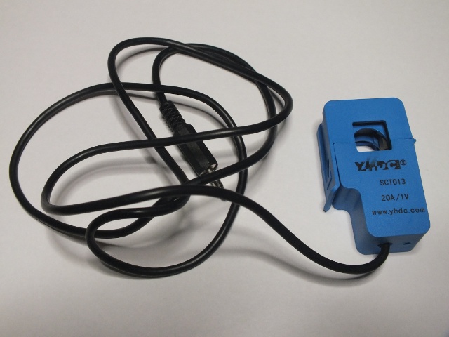
A current transformer (CT) is used for measurement of alternating electric currents. The most common design of CT consists of a length of wire wrapped many times around a silicon steel ring passed ‘around’ the circuit being measured.
Current transformers are used extensively for measuring current and monitoring the operation of the power grid. The primary circuit is largely unaffected by the insertion of the CT.
Clip-on current transformers are useful for measuring AC current because they can be easily attached to wire being measured and they provide electrical isolation from mains power. To do some AC measurements I ordered AC 20A SCT-013-020 Non-invasive Split Core Current Transformer. I selected it because it was not too expensive, STC-013 current transformer series has become quite popular because they are used by OpenEnergyMonitor project, and this particular model has suitable voltage output (has internal shunt resistor).
YHDC SCT-013-020 Split Core Current Transformer data:
Input Current : 0A-20A
Output voltage: 0-1V
Core Material : Ferrite
Wire hole: 13 mm
Dielectric Strength : 6000V AC/1min
Non-linearity ±3%(10%-120% rated input current)
Manufacturer: Beijing YaoHuadechang Electronic Co., Ltd
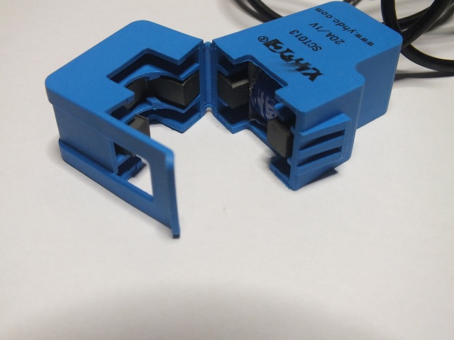
Here is AC 20A SCT-013-020 Non-invasive Split Core Current Transformer opened:
This model outputs 1V signal when it gets 2oA flowing through the wire being measured. This signal level is well suitable to be connected to an oscilloscope or PC sound card line level input. The 3.5mm plug on the end of the cable has even suitable pin-out for direct connection to sound card (current transformer output connected between tip and shield).
I did some measurements with sound card, signal generator and oscilloscope. The mains waveform showed well on PC screen with Soundcard Oscilloscope (from http://www.zeitnitz.de/Christian/scope_en). I first tested with line level input that worked well. I also tried connection to PC sound card microphone input, and it worked with more sensitivity (senses lower currents) but with limitation on highest current it can measure (I would not try to measure more than 1-2A).
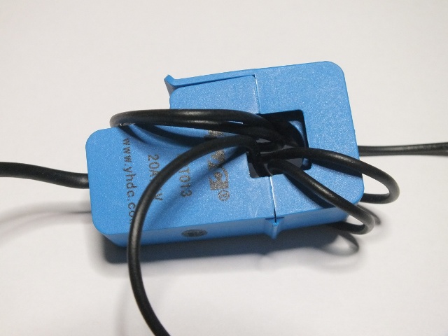
I did some quick testing with signal generator and oscilloscope to get idea of the frequency response. To get strong enough signal on the output, I fed the signal from function generator several times through the current transformer to get stronger output signal:
I did some measurements, and it seems that this current transformer does what it is supposed to do well. The output measurements were what I expected. I was also interested in the frequency range that works by feeding different frequencies and measuring the output. In my measurements the output signal did not change much in 50 Hz to 20 kHz frequency range. So this is pretty good frequency response.
I also wanted to know what is the output impedance on the signal output. I measured that the output impedance is around 50 ohms (shows as 50 ohm resistor on multimeter).
For more information on STC-013 series current transformer properties take a look at the following document: Yhdc SCT-013-000 Current Transformer report tells the the properties of the Yhdc Current Transformer (and its suitability for use with the OpenEnergy monitor). This document tells the details of Non-invasive AC current sensor (100A max), Model SCT-013-000. It has no internal burden resistor, but zener diodes limit the output voltage in the event of accidental disconnection from the burden.
I found that the output resistance of SCT-013-000 was around 100 ohms.
Product pages with information on STC-013 series current transformers:
AC 20A SCT-013-020 Non-invasive Split Core Current Transformer
YHDC Non-Invasive AC Current Sensor [100A/30A]
YHDC 13mm hole Split core current transformer


4 Comments
website says:
great post, very informative. I ponder why the other specialists
of this sector do not notice this. You must proceed your writing.
I am confident, you’ve a great readers’ base already!
Amal Raj says:
Hi I want to test yhdc sct013-000 100A:50mA using DMM. I don’t know how to measure Current and Voltage with load and unloaded. I have inserted 40W lamp probe into CT. How do i test using DMM? can you pls tell in detail?
Tomi Engdahl says:
If you are powering 40W lamp with 230V power source, it takes almost 200 mA of current.
The current transformer outputs 1V signal when it gets 20A current through it. With around 200mA, you should get about 10 mV AC at the current transformer output. Measure it with sensitive multimeter AC measuring range – hopefully your multimeter can measure this low AC voltages.
Tomi Engdahl says:
Using a Split Core Current Transformer
https://www.youtube.com/watch?v=-3DRaMcHf5w
Home Energy Monitor Project: Current
https://www.youtube.com/watch?v=Z3YSHhS39Bc
This is a potentially very dangerous project. It involves working with AC house power (120/240V) that if not treated with the proper care can cause bodily injury and/or destruction of property.