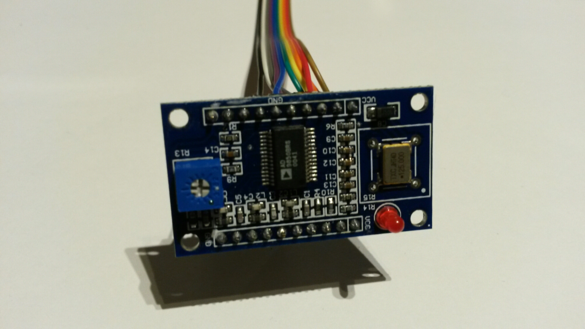
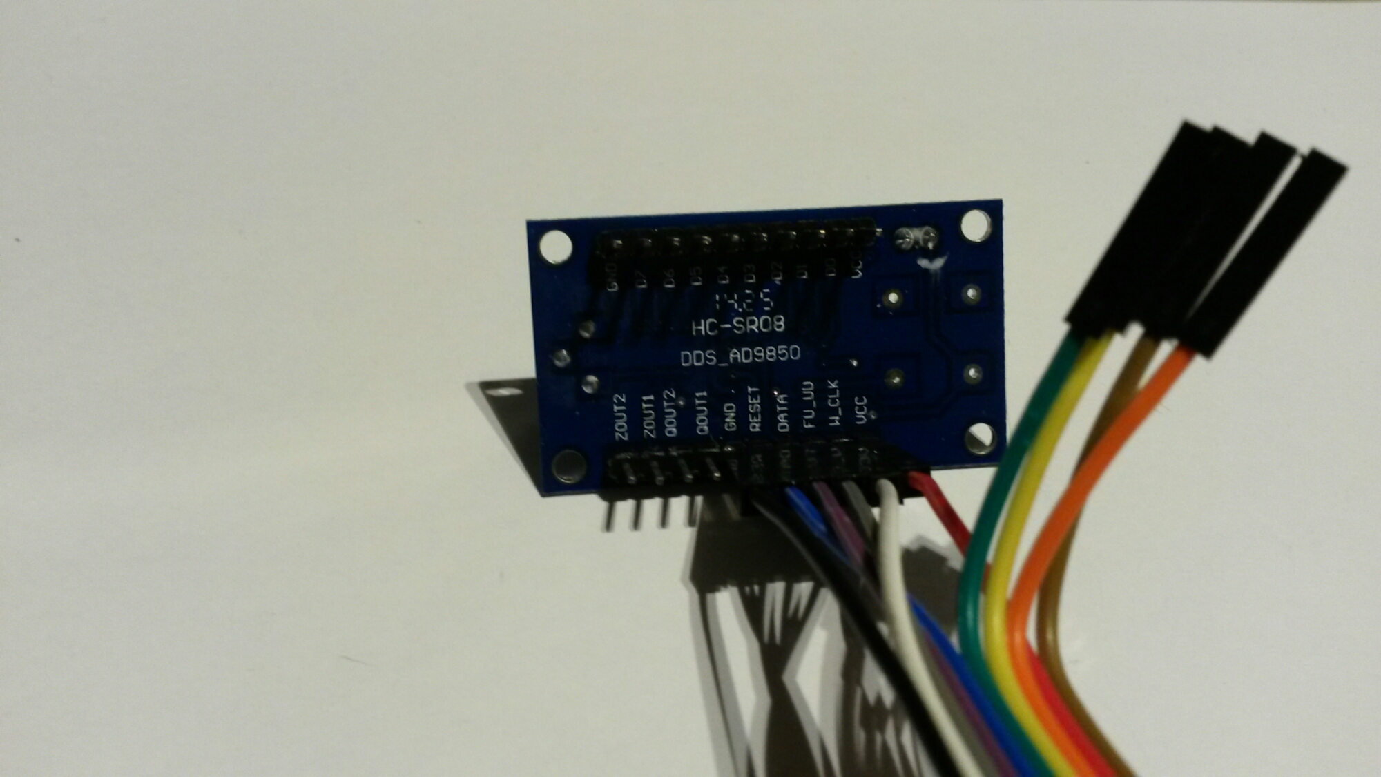
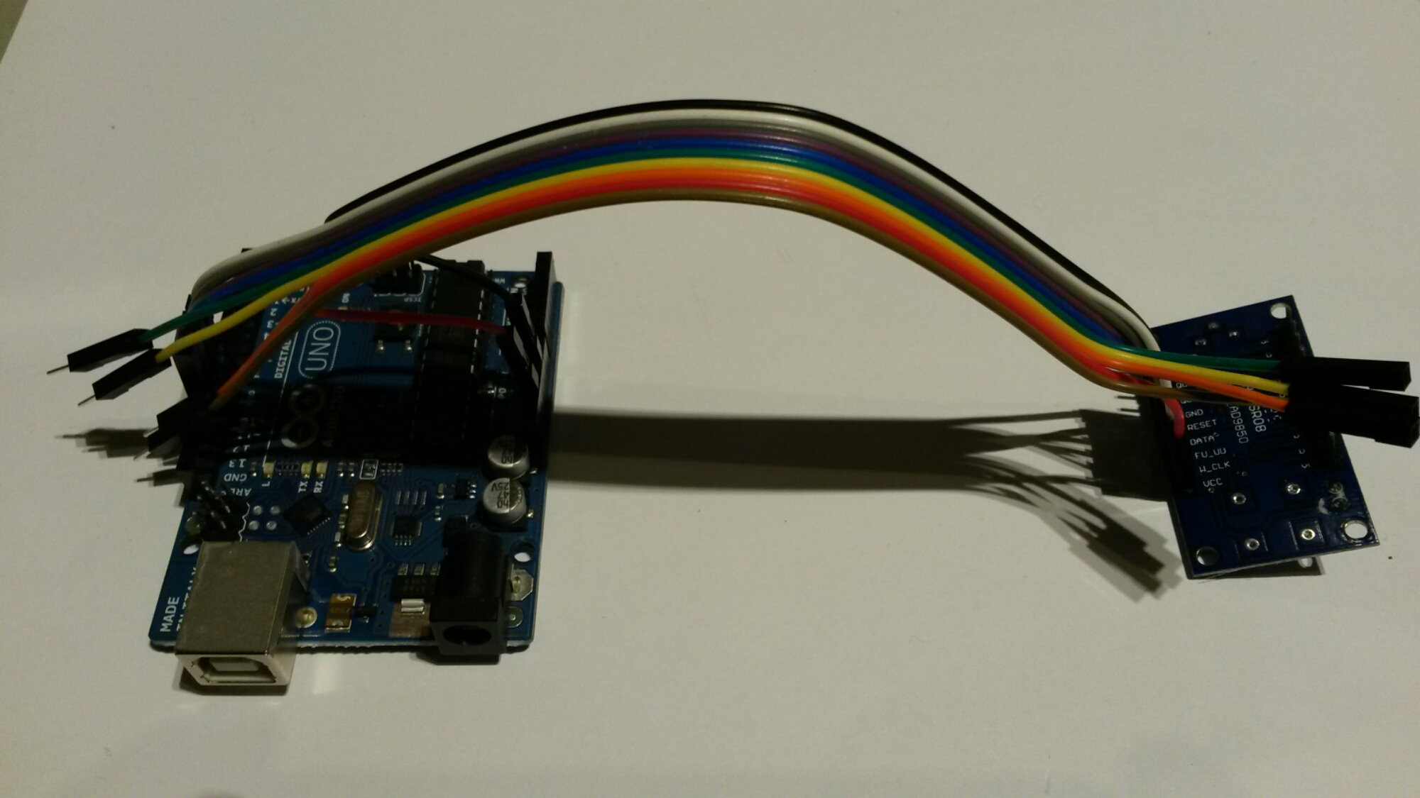
For some RF tests I sometimes need to generate different higher frequency signals than normally available from general purpose function generator. For this purpose I bought a cheap AD9850 module to generate different frequency RF signals. This AD9850 module can generate frequencies in 0-40 MHz frequency range (sine wave output).

For initial testing I successfully used instructions and code for web page Testing an eBay AD9850 DDS module with Arduino Uno.
Arduino Pin 8 - connect to AD9850 module word load clock pin (CLK)Arduino Arduino Arduino Testing an eBay AD9850 DDS module with Arduino Uno page notes that there are super inexpensive DDS modules being sold at cheaper price than you can buy the 9850 chip by itself. To get any output from one of these you need to send 40 bits of data to the chip. It’s all explained in the official Analog Device datasheet.
I successfully used the provided example code for AD9850 on a UNO prototype shield, and testing it in single frequency mode. The code had simple function call sendFrequency(10.e6); to set frequency. I tried several frequencies and got what I expected on my oscilloscope/multimeter.
Instead of using proto shield I just wired the module directly to Arduino. Example code worked well, and I could generate different frequencies easily by changing frequency in frequency setting function call. I only tested generate one sinewave frequency output mode (The module can output sine wave, square wave, two sine wave and two square-wave output). I got sinewave from ZOUT1 and ZOUT2. The module gave also square wave output from QOUT1 and QOUT2 (the trimmer on the board controls signal pulse width).
I tried and it works like i expected. It works very well.
Link to page where to buy: AD9850 DDS Signal Generator Module 0-40MHz IC Test Equipment
Some related links:
Testing an eBay AD9850 DDS module with Arduino Uno – good instructions to get started
Build Your Own Antenna Analyser for under $50 – measurement instrument based on AD9850 DDS module
Arduino Antennen Analysator – DG7EAO – another antenna meter design that uses AD9850 DDS module


13 Comments
Tomi Engdahl says:
HomeBrew AD9850 Arduino DDS VFO on the Cheap!
https://www.youtube.com/watch?v=W_dlocgMEpI
HomeBrew DDS VFO built using AD9850 DDS module, Arduino processor, & Backlit LCD display all for about $25 bucks. Uses open source Arduino code & junkbox enclosure & small parts.
Tomi Engdahl says:
experimental radio test – USB controlled SDR with SA612 and AD9850 DDS
https://www.youtube.com/watch?v=UTdNYhvF_dw
Tomi Engdahl says:
AD9850 Signal Generator
https://www.youtube.com/watch?v=1Mjl6TPx9OA
Tomi Engdahl says:
Interactive Design Tools: Direct Digital Synthesizers : AD9850 Device Configuration Assistant
An applet for calculating codewords and harmonics images in the AD9850 DDS Synthesizer.
http://designtools.analog.com/dt/dds/ad9850.html
Tomi Engdahl says:
Interesting looking project:
Bode plots on an oscilloscope
http://hackaday.com/2013/08/19/bode-plots-on-an-oscilloscope/
The basic idea behind [Dave Jones]’ impromptu Bode plotter is to configure a frequency generator to output a sine wave that ramps up over a period of time. Feed this sine wave through a filter, and you have amplitude on the vertical axis of your ‘scope and frequency on the horizontal axis. Boom, there’s your Bode plot.
[Andrew] did [Dave] one better by creating a small circuit with an Arduino and an AD9850 sine wave generator. Properly programmed, the AD9850 can ramp up the frequency of a sine wave with the Arduino outputting sync pulses every decade or octave of frequency, depending if you want a linear or log Bode plot.
Bode Plot on an Oscillscope
http://reibot.org/2013/08/16/bode/
Tomi Engdahl says:
Arduino DDS Shield
http://m0xpd.blogspot.co.uk/2013/02/arduino-dds-shield.html
I represented the DDS module as a component in Eagle
The module only took up a small fraction of the available area on the shield, so I added a couple of dual flip-flops to generate a quadrature squarewave output for future games
Tomi Engdahl says:
Arduinofied QRP radio beacon
http://hackaday.com/2013/02/24/arduinofied-qrp-radio-beacon/
[m0xpd] is back again, this time using the AD9850 DDS module as a radio beacon with an Arduino.
Arduino Beacon
http://m0xpd.blogspot.co.uk/2013/02/arduino-beacon.html
Tomi Engdahl says:
Project to look at:
0-40Mhz, Sine wave generator for $25
http://www.instructables.com/id/0-40Mhz-Sine-wave-generator-for-25/
With only 4 control wires we can control the board via the arduino. This gives us a variable sine wave generator that we can control to give us a very nice sine wave from 0 Megahertz up to around 40 Megahertz at almost a full volt peak to peak.
I decided to use a $7 LCD keypad to give some on screen visual indication of the frequency plus a means of controlling the frequency quickly and easily.
The code to upload to the Arduino, can be relatively straight forward.
0-40Mhz, Sine wave generator $25.
http://tobyrobb.com/wordpress/?p=577
I decided to use an LCD keypad to give some on screen visual indication of the frequency plus a means of controlling the frequency quickly and easily.
Tomi Engdahl says:
This looks like
AD9850 useful test sketch for Arduino(-s)
https://gist.github.com/raivisr/3861473
Serial comms – 9600, NewLine (0x0A) denotes end of input,
f 10000 – set frequency
s 20 20000 10 1000 – sweep from frequency to frequency using this step size in that many milliseconds
o 10 10000 5 3000 – oscillating sweep from frequency to frequency and back using this step size in that many ms
Tomi Engdahl says:
Other projects:
ad9850-arduino
A simple library for arduino to control an ad9850 DDS synthesizer
https://code.google.com/p/ad9850-arduino/
DDS-AD9850 + Open oscilloscope – Lxardoscope
http://www.elecfreaks.com/2110.html
Here we will show you how to control AD9850 module by Arduino, and then show the output wave by Lxardoscope, which is an Arduino based oscilloscope for Linux, using the Xforms library.
Tomi Engdahl says:
Exercises/Experiments >
AD-9850 DDS Synthesizer
http://rockingdlabs.dunmire.org/exercises-experiments/ad-9850-dds-synthesizer
Tomi Engdahl says:
Some measurement on the module:
For sine wave output the outputs seem to have around 0.5V amplitude and around 100 ohms output impedance.
Tomi Engdahl says:
EZAD9850 Library
https://hackaday.io/project/4477-ezad9850-library
The EZAD9850 Library will get you up and running on the Arduino with inexpensive AD9850 based frequency generator modules.
This Arduino library makes easily available control of an AD9850 module’s frequency and phase as well as starting and stopping frequency generation. Useful for a variety of radio projects and as a sine-wave generator. Operates from 0 – 40 MHz.