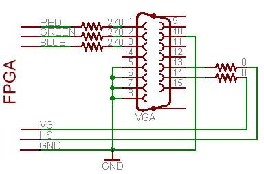
This is continuation to Interesting VGA hacks hacks posting. Interesting VGA hacks hacks was concentrated on using VGA card for nontraditional uses, this posting on the other hand concentrates on generating VGA signals with other hardware than VGA graphics card.
It seems that modern microcontrollers are well suited to display information on analog VGA monitors:
AVR VGA generator implements VGA on microcontroller. This AVR-based VGA generator uses ATmega1284 to output a stable VGA signal. Anyone who’s looked into the VGA standard will know that this is quite an accomplishment. Red, green, and blue each get their own two-bit range selected via a set of resistors for a total of 64 colors. 128×96 pixel video is up and running.
Arduino Uno output to VGA monitor project shows how you can output VGA signals to a monitor, turning your Uno (or similar) processor into a “video card”. The biggest challenge is to ge the pixel data out – it just can’t be done with software running on this processor and we also don’t have enough memory to even hold those pixels all at once. The fastest way we can get bits “out the door” is using the SPI hardware.
Code: VGA RGB Signal project Connect Arduino to VGA input on TV. You can find the circuit diagrams and code at Github at arduino-vgaout.
VGA interfacing AVR microcontrollers project shows us how to push data to a VGA monitor from your AVR project. It turns out that it is pretty simple, requiring only n open port and a few resistors and diodes. Well, it is that simple for the most basic version which gives you 56×60 pixels. Version 2 outputs 240×240 resolution.
Microcontroller VGA Interface projects page (tinyvga.com) show examples how to use Microchip PIC 16F84 VGA Output and several versions for Atmel AVR VGA outputs.
Other popular way to generate VGA signal is to use FPGA chips:
FPGA VGA Resistor DAC page tells that VGA is a very friendly protocol to use with FPGA’s and CPLD’s and because of this we can easily build video controllers with basic PLDs. The VGA protocol itsself is slow, running around the 20-30 MHz range depending on the resolution chosen, meaning that we can even breadboard or wire-wrap prototype designs!
VGA Controller (VHDL) page shows a VHDL source code of a VGA interface controller. It generates the signal timing for a VGA interface, offers configurable VGA mode (i.e. resolution and refresh rate). The page has an example implementation using a DE2-115 development board.
FPGA Tutorial 4. VGA in VHDL on Altera DE1 Board video tutorial I will show how to program VGA interface in VHDL, suing DE1 Altera board. Eventually it will program a simple game.
Pong Game page shows that FPGAs can become video generators easily. The pong game consists of a ball bouncing on a screen. A paddle (controlled from a mouse here) enables the user to make the ball bounce back up.
Draw VGA color bars with FPGA in Verilog page mentions a FPGA workshop. The most useful comments will be in the VGA controller module we wrote: vga640x480.v.
Design Recipes for FPGAs – A Simple VGA Interface article gives tips for VGA implementation using FPGA.
Other related information:
VGA signal timing calculation using MCU

107 Comments
Tomi Engdahl says:
https://hackaday.com/2024/06/12/displays-we-love-hacking-dsi/
Tomi Engdahl says:
https://hackaday.com/2024/05/08/displays-we-love-hacking-lvds-and-edp/
Tomi Engdahl says:
https://hackaday.com/2024/01/25/displays-we-love-hacking-parallel-rgb/
Tomi Engdahl says:
https://hackaday.com/2024/06/05/displays-we-like-hacking-hdmi/
Tomi Engdahl says:
https://hackaday.com/2023/12/21/displays-we-love-hacking-spi-and-i2c/
https://hackaday.com/2023/10/02/displays-we-love-hacking-the-hd44780-family/
Tomi Engdahl says:
RPi Pico Video4
https://hackaday.io/project/196770-rpi-pico-video4
A RPI Pico RP2040 board with 4 composite video outputs, 8 inputs and switched power
The Pico Video4 Display is a stand-alone RPi Pico RP2040 board, connected through USB-C.
This board provides up to 4 analog composite video display interfaces with integrated frame buffer memory accessible through SPI. The 4 video outputs are accessible through 1 RCA connector and 1 VGA DB15-HD connector that uses the red, green and blue channels for the composite signal.
The heart of this design is the VLSI VS23S040 chip. PAL and NTSC output formats are supported. Currently 4 resolutions are implemented: NTSC 320×200 or 426×200 with 256 colours and PAL 300×240 or 500×240 with 256 colours. The chip has a 1Mbit framebuffer per channel