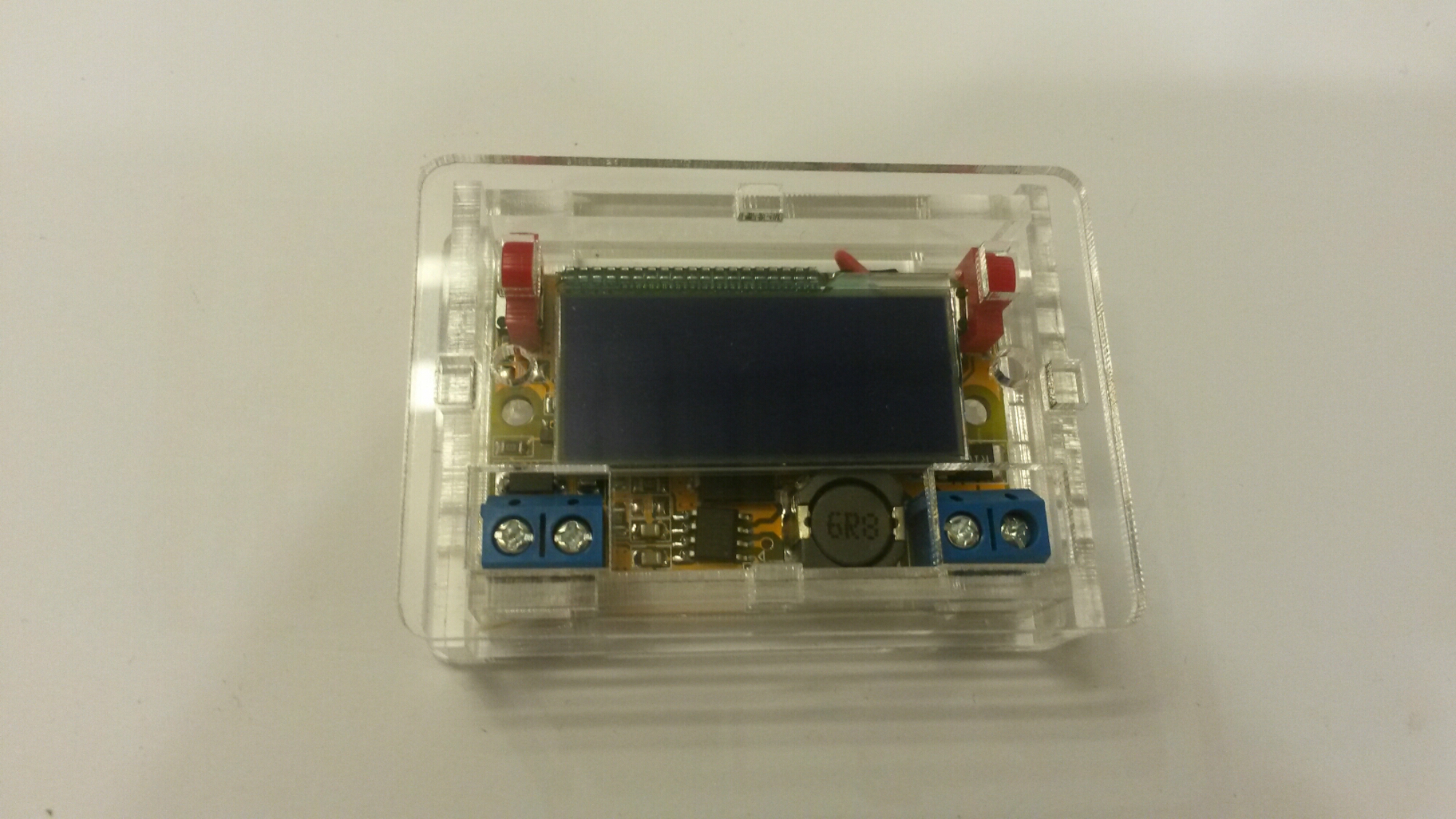
I needed a new small power supply for my electronics project table. I was checking several options for a lab power supplies, but when I saw DC-DC Step Down Power Supply Adjustable Module With LCD Display With Housing Case I decided that I could use it to build easily the power supply I need. In this case I wanted adjustable voltage and also wanted current meter (I did not need current limiting).
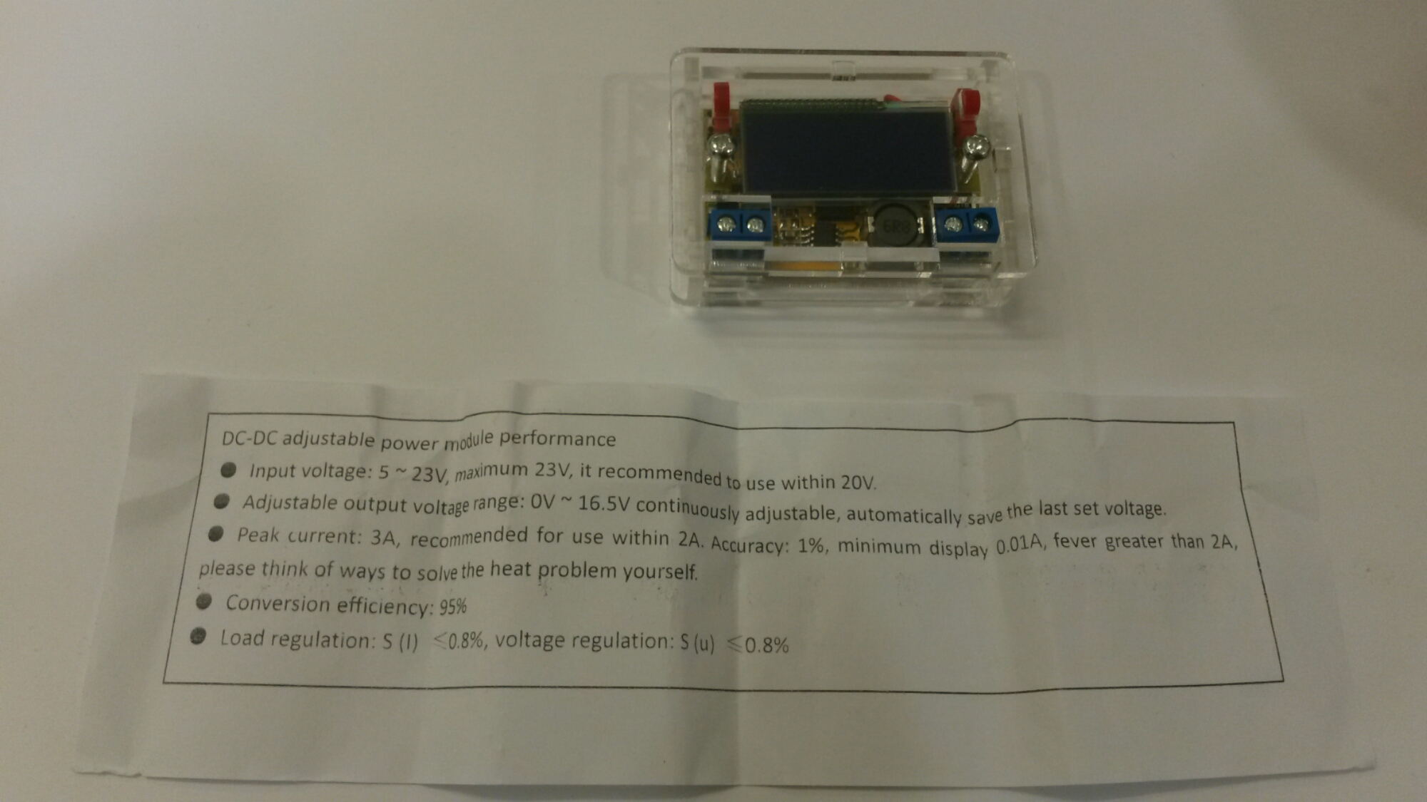
DC-DC Step Down Power Supply Adjustable Module With LCD Display With Housing Case is an adjustable DC-DC step down power supply module with LCD display and housing. The price was pretty cheap (this one costs 5.34 Euros / $ 5.99 , there is also cheaper version without case). The module promises to give out 0V~16.5V (Continuously adjustable) voltage at up to 2A continuous current (peak current 3A). The input voltage is said to be 5~23V. The documentation says that best voltage is 20V.
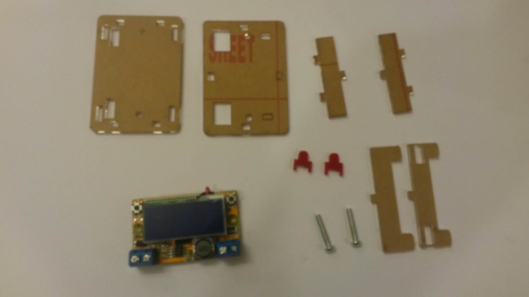
DC-DC Step Down Power Supply Adjustable Module With LCD Display With Housing Case package included:
1 x DC-DC step-down power suppl module
1 x Transparent shell
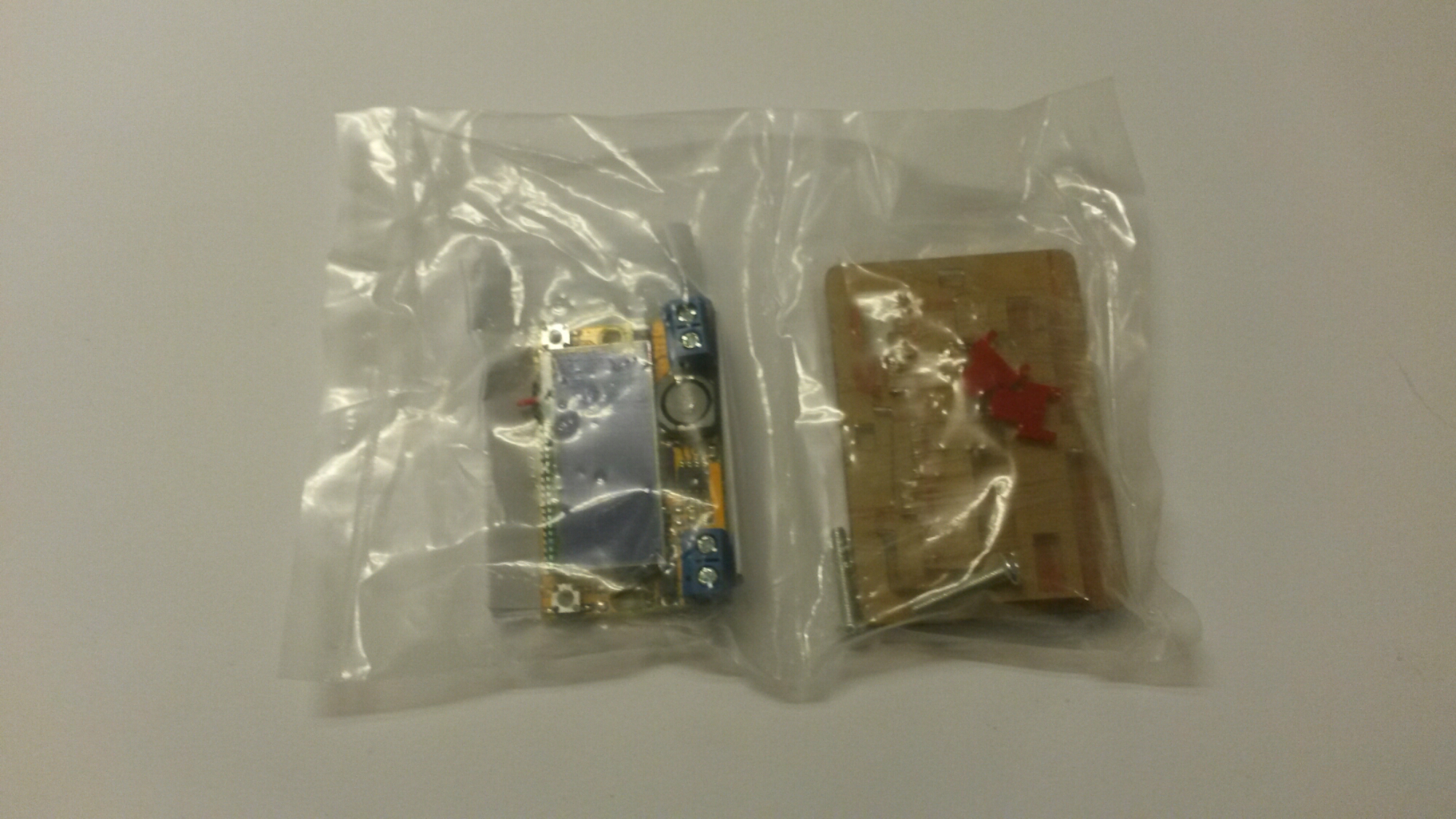
The parts came packaged to a sealed plastic bag.
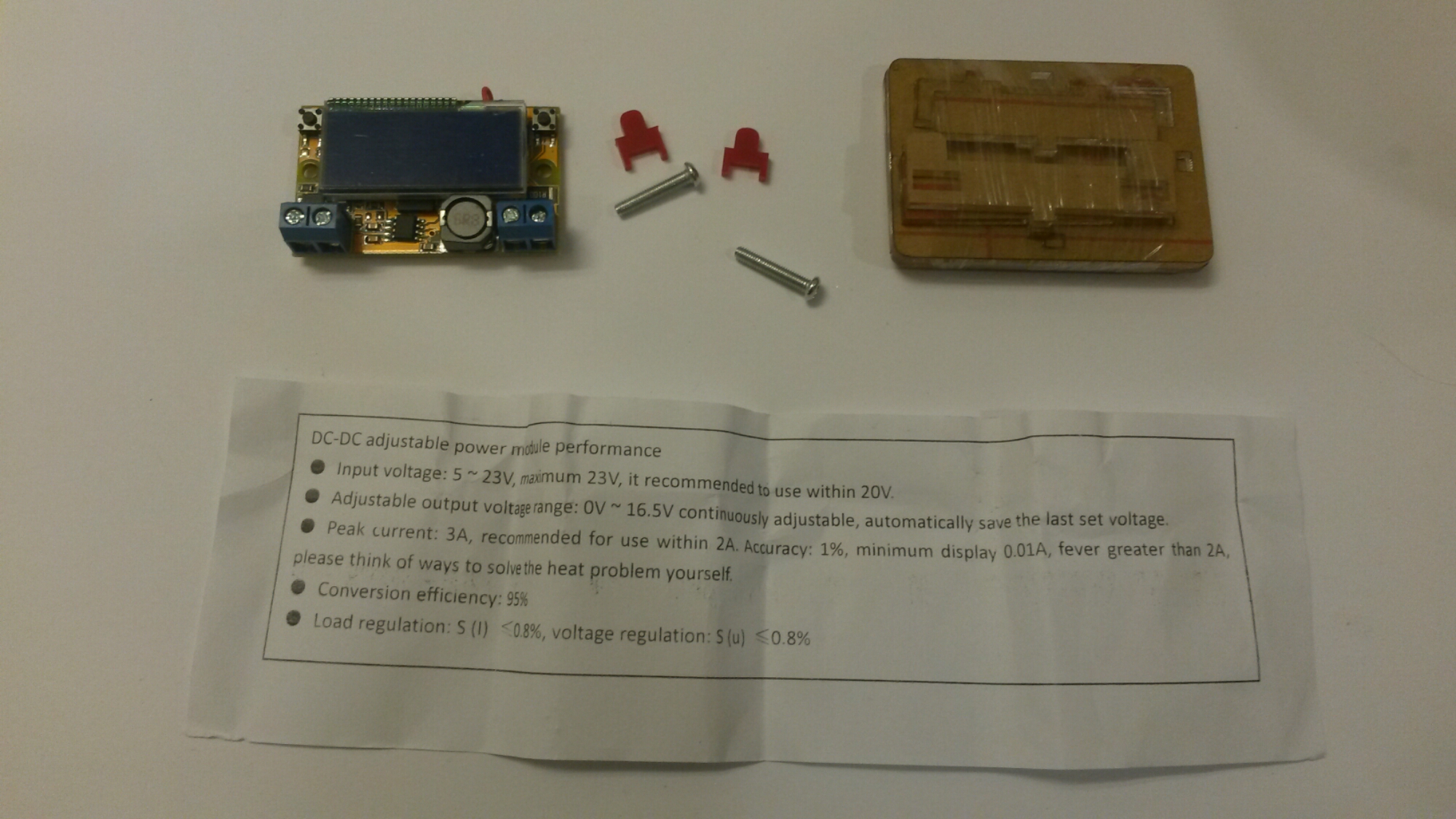
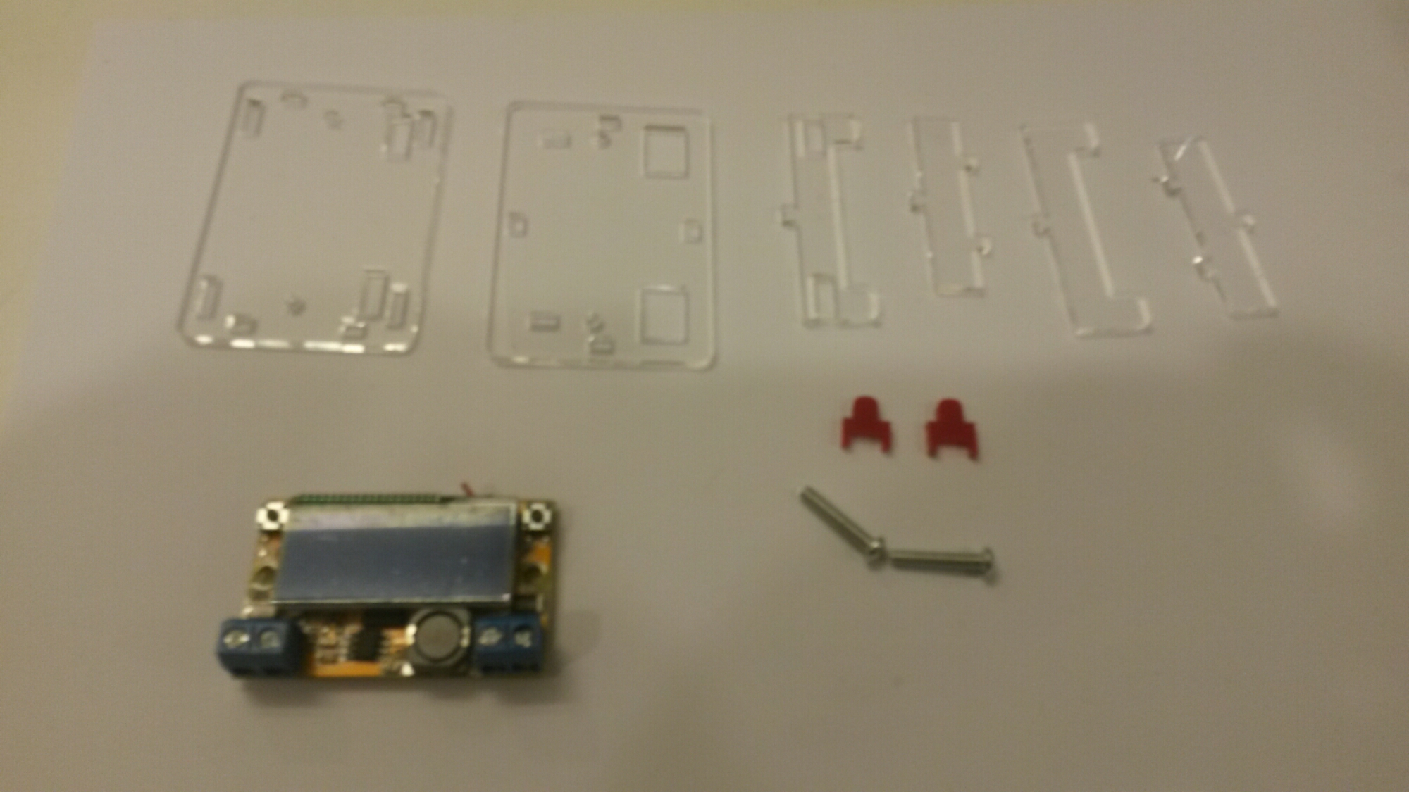
Parts taken out of bag:
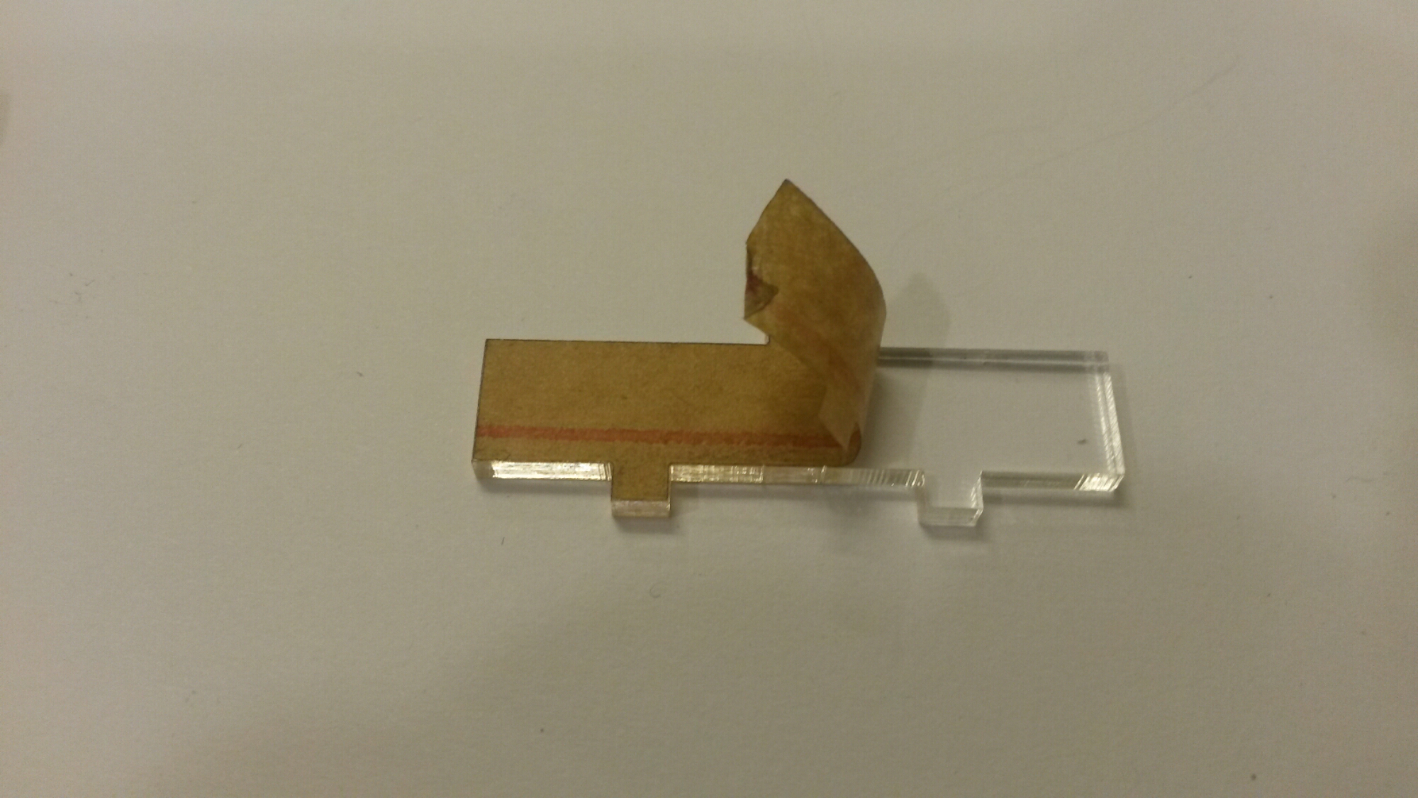
Removing the protective layers from laser cut plastic parts:
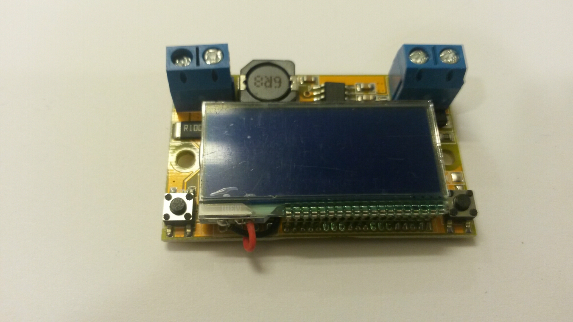
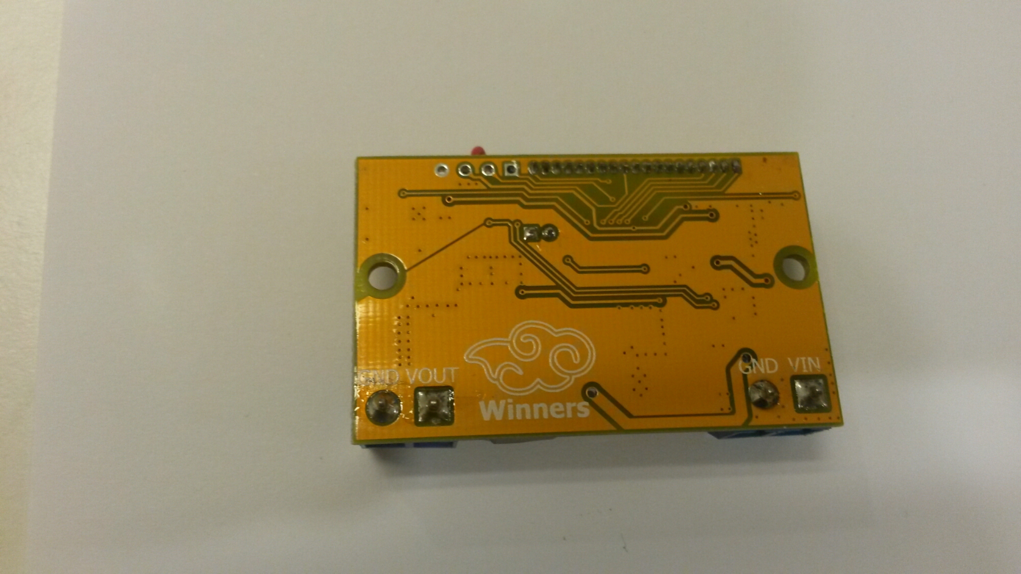
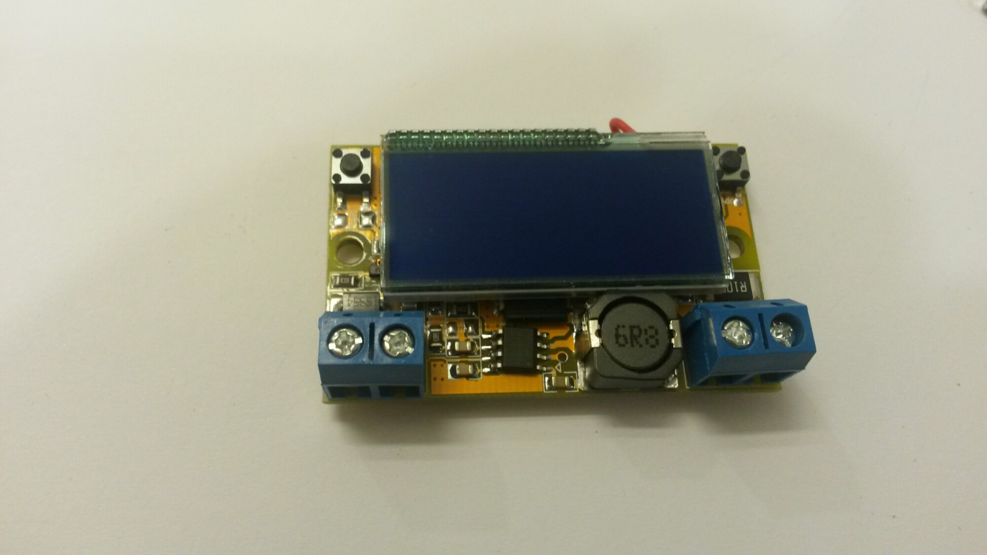
Main module size (the circuit board) is 50mm x 30mm x 12mm(LxWxH).
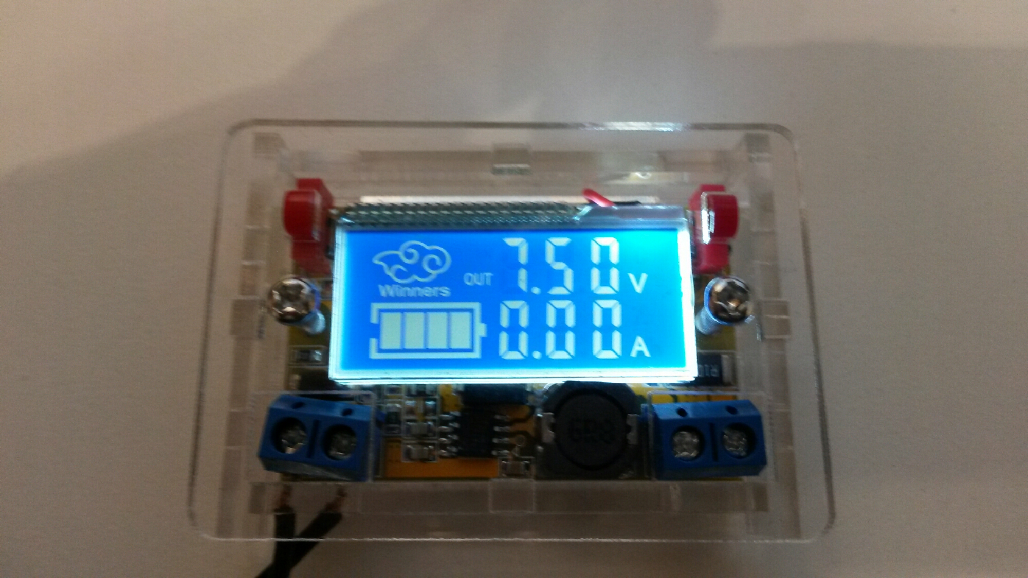
In my testing I powered it with 12V DC so I got around 0-10V voltage range.
Here is picture of my module in use. I powered the module from 12V DC power. It worked well and was able to give out voltages from 0V to slightly over 10V.
The buttons worked for for adjusting the output voltage. The voltage meter showed the output voltage and the current meter showed the current going to output. The voltage setting is stored to internal memory so that setting will stay the same when you power down the module and power it up again later. Because the power supply is based on switch-mode technology, there is some switch mode noise on the output (around 20-30 mV of noise at around 400 kHz when output was set to 3.3V).
The were some downsides on the module. For example the meters were not very accurate. The voltage meter showed around 3% lower reading than my two multi-meters. Current meter also showed 2% less than real current (verified with two multi-meters). Also the case had issue – if you tighten the screws all the way, it causes that the buttons are in pressed down state all the time.
The module promises 2A continuous current and 3A for short time. There is no adjustable current limiting. The short circuit current to multi-meter when I did test was around 5A (short test did not damage the module). I also did accidental test by wiring the input power wrong way – the module was not damaged by this mistake.
I would say that the DC-DC Step Down Power Supply Adjustable Module With LCD Display With Housing Case was well worth of the price. If you don’t need the case, there is a cheaper version without case available.
5 Comments
Tomi Engdahl says:
The converter is based onMPS MP2307 IC
https://www.monolithicpower.com/Products/Product-Detail/238/Step-down(Buck)/SwitchingRegulators/DC-DCPowerConversion/Converters/MP2307
The MP2307 is a monolithic synchronous buck regulator. The device integrates 100mΩ MOSFETS that provide 3A of continuous load current over a wide operating input voltage of 4.75V to 23V.
Tomi Engdahl says:
Here is teardown of a more expensive psu module I also have considered:
Buck-boost module teardown & test
https://www.edn.com/electronics-blogs/benchtalk/4460293/Buck-boost-module-teardown—test?utm_source=Aspencore&utm_medium=EDN&utm_campaign=social
A whole series of interesting and seemingly well-designed and -made power supply modules have come out of Rui Deng (Hangzhou Ruideng Technologies) of China over the last year or two.
The outputs aren’t super-quiet, but fine for general use. I may add output filters.
The LTC1871 on the little daughtercard is a boost converter running at a bit over 100 kHz.
The XL7005A is a buck switcher-on-a-chip, running at 150 kHz. In fact, the output switch is a Sziklai pair
The TL594 is a general PWM control IC, similar to the classic TL494, and runs at 68 kHz
The STM32F100C8 is an ARM Cortex-M3 microcontroller with all the usual trimmings.
What’s conspicuous by its absence? Yeah…switching MOSFETs. There are two SMT parts clamped under the bottom edge of the heatsink. I think we’ve found our transistors. No…I’m not removing the sink.
As I said, this crazy arrangement of three switching converters had me perplexed at first. I originally assumed there’d be one switcher
Yes… It seems the input (6-40 V) is converted to an intermediate 35.7-40 V, which is then stepped down to the desired output. That’s a bit surprising, given that losses tend to be exacerbated with high buck step-down ratios. I guess the designer felt this to be the best trade-off. If it works, who am I to complain?
That third switcher, the XL7005A? It appears to generate 5V, and there are two (I think) 3.3V linear regulators as well. The µC, LCD, and op-amp need juice too.
Tomi Engdahl says:
After about two years ago (intermittent use on lab table) this module stated to fail:
The problem was that the voltage reading on the screen does not match what comes out!
When I set the output to 9V, the module puts out around 6.3V.
If I increase or decrease the voltage, the output voltage changes, but is around two volts or more off.
Annoying that this module was quite short-lived.
Tomi Engdahl says:
Winners Adjustable DC Power Supply: Walkthrough and review
https://flyingcarsandstuff.com/2016/09/winners-adjustable-dc-power-supply-walkthrough-and-review/
a little adjustable power supply, purchased off ebay for dirt cheap.
It can take between 4.5 and 23V in (recommended to stay below 20V) and has a 1.5V drop-out.
It’s claimed that it can source up to 2A continuous (with 3A surges)… I dunno
Winners Adjustable DC Power Supply (from ebay): review and demo
https://www.youtube.com/watch?v=Hh0tqsXY7P8
Tomi Engdahl says:
On my problem with power supply I re-read the product page and found calibration instructions.
Maybe I should check if calibration helps.
And indeed it helped. Now the power supply meter shows again the voltage correctly.
Maybe I had accidentally done calibration without knowing…
https://www.banggood.com/DC-DC-Step-Down-Power-Supply-Adjustable-Module-With-LCD-Display-With-Housing-Case-p-1038740.html?rmmds=buy&cur_warehouse=CN
Calibration method:
Under power off situation, Holdind left button and power the supply,when the display begin flashing, release left button, with multimeter measuring the output voltage, by press the left and right button ,adjust the multimeter measuring voltage near 5V, such as 5.00V ,4.98V or 5.02V is ok too,at this situation,please ignore the displaying on this item. After adjustment,please power off it and then power to it again, then the calibration is completed. Errors can be calibrated in 0.04V, if the error is greater, you can try to calibrate it again.