I have earlier written on using DMX-512 controlled dimmer to control mains powered lamps. It works, but is expensive and traditional incandescent lamps are going out of fashion. LEDs are the future, so a cheap easy to use board for controlling low voltage LEDs with DMX-512 signal are needed.
To experiment with LED conrolling I got one 72W 3 Channel DMX512 Encoder Decoder Board Codering Module for RGB LED Stage Light board from Banggood. This cheap (less than $4) board promises to provide gray-scale 0-100% dimming with 256 * 256 * 256 gray-scale. The board is powered from DC12 ~ 24V and can drive up to 72W (2A*3 Channel). This is exactly what is needed to power high power RGB LEDs or RGB LED strip. Connected with DMX512 controller, the controller will follow the effect of changes on generated PWM outputs. Recommended applications are high-power full-color wall wash lights, spot lights, buried lights, underwater lights, stage lights, tunnel lights.
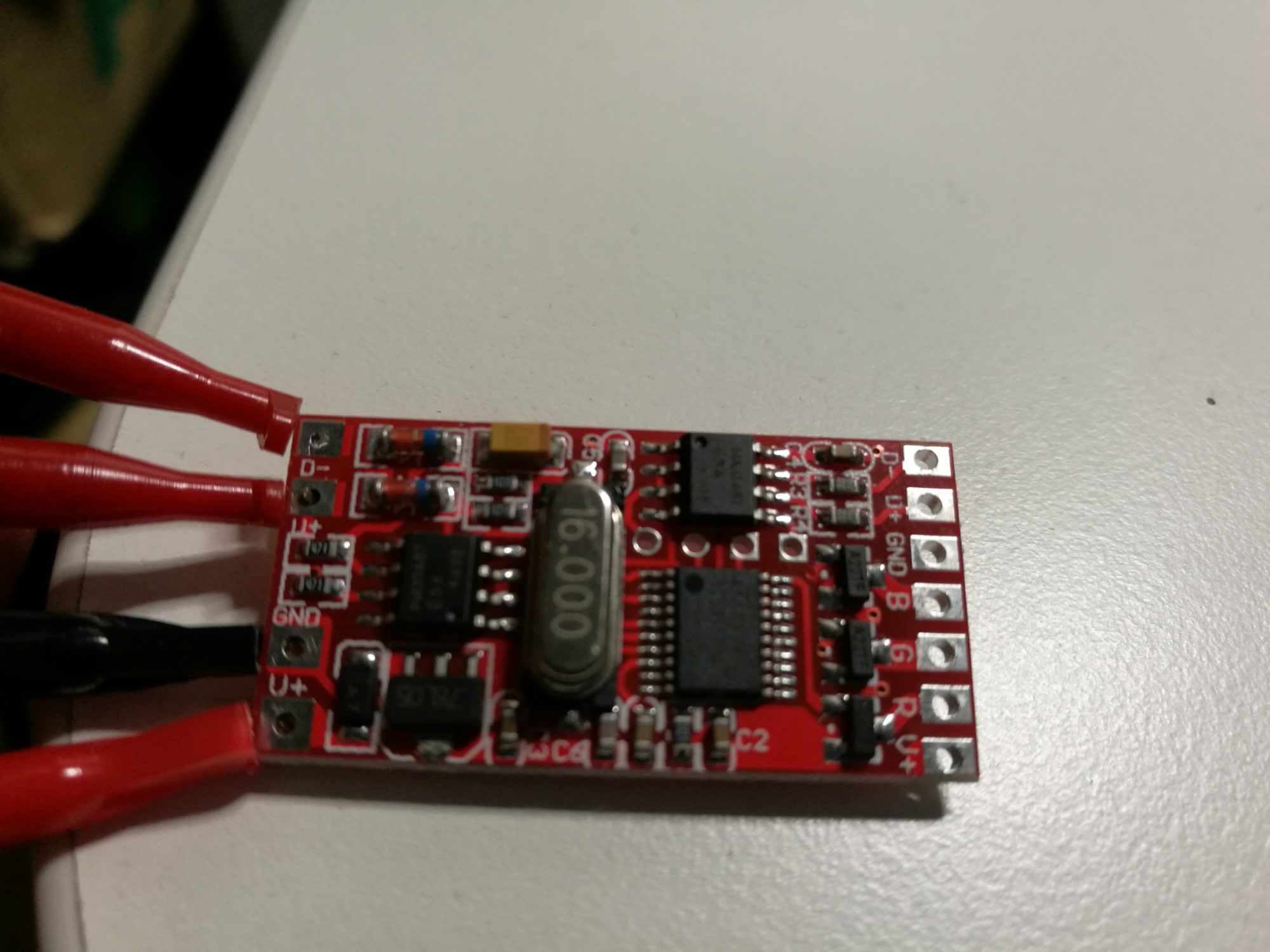
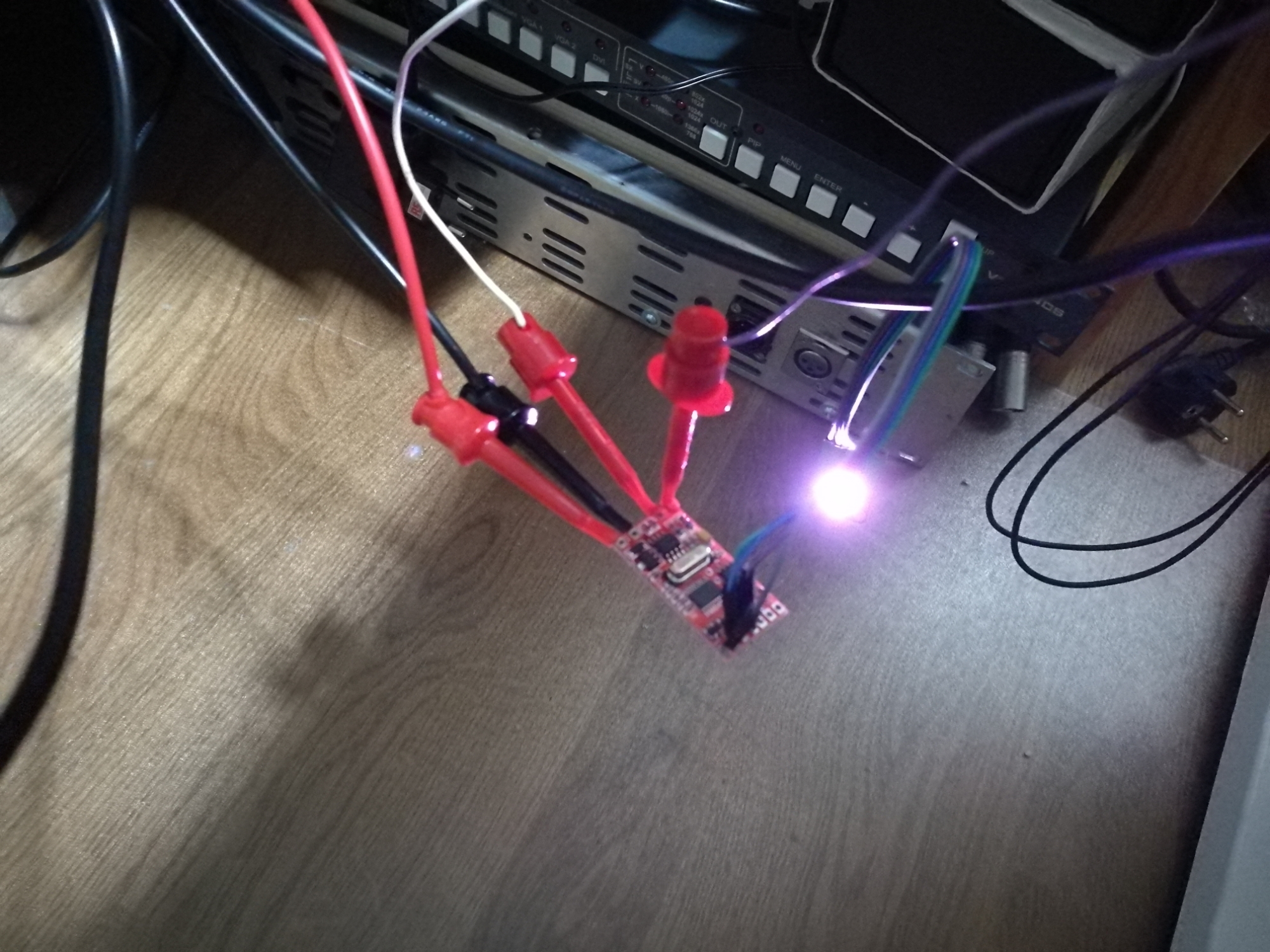
Here is the board (with some cables connected with test clips).
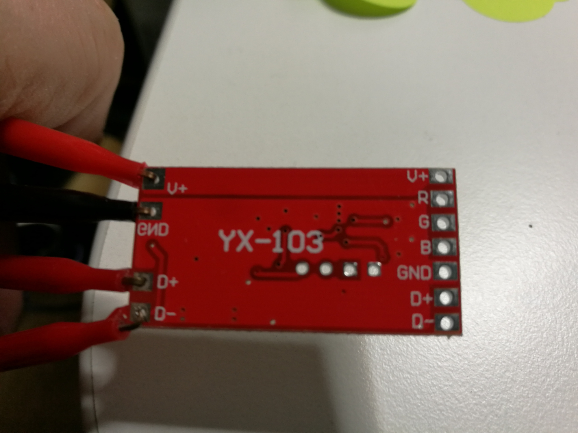
Here is a look at the backside
According to the product documentation when not associated DMX512 controller will automatically run the built-in effects (colorful hopping, gradient) – this worked as promised. Next test was to use Q Light Controller Plus software and OpenDMX USB DMX-512 output adapter (same setup as I have successfully used earlier) to control the module.
In this testing I needed some suitable RGB LED to control. I decided to use one RGB LED moduke designed for Arduino I had around (MF DIY RGB SMD LED Module for Funduino).
This LED module (MF DIY RGB SMD LED Module for Funduino) is designed to work with 5V Arduino, so running it from 12V instead of 5V could easily overheat the LED and/or tiny current limiting resistors on board. I finally decided to try my luck by powering theDMX512 Encoder Decoder Board from 8V power supply (the board logic circuits power supply is based on 7805 type regulator, so it should run nicely down to 8V). The testing at 8V was success – both RGB LED and decoder worked well. The decoder board always responds to DMX-512 channels 1-3 (it does not have DMX-512 address switches in it).
I measured that the LED PWM control frequency is 488 Hz, which should be high enough that you can’t see any flickering on LED dimming.
The electronics on the board seem to consist of two MAX1487 RS-485 transceivers, 78L05 regulator, ST 8s003f3p6 microcontroller (STM8 core), 16 MHz crystal, three FETs and some supporting components.
72W 3 Channel DMX512 Encoder Decoder Board Codering Module for RGB LED Stage Light board page as pretty much all the basic information to get the board working, but there seems to be some things are not entirety right. For example this drawing:
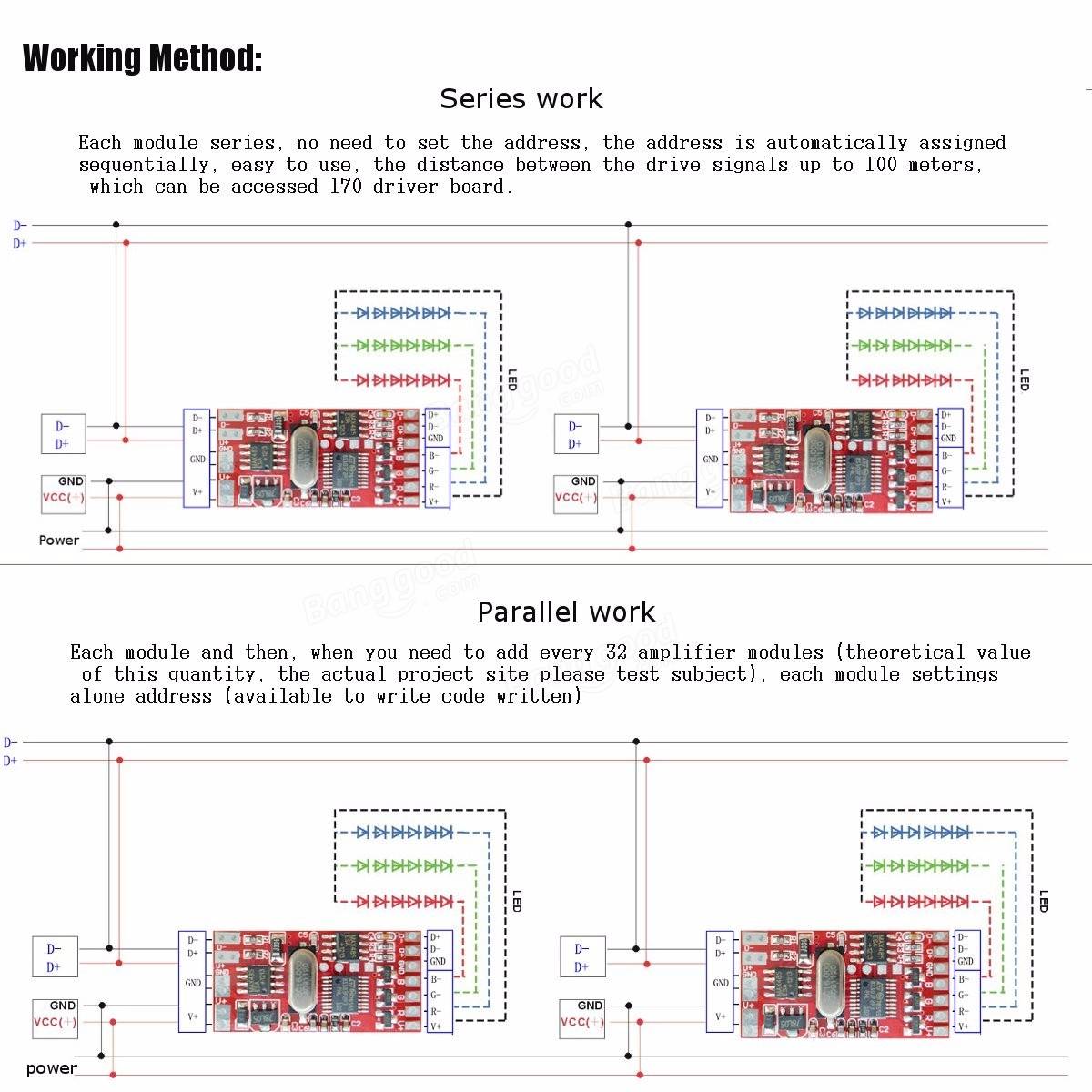
The lower pcture parallel method seem to be as it should. But the upper series work seems to have the exactly same drawing – I think that the second decoder board should get the signal from the output of the first board, otherwise connection does not make sense. The boards have for a reason DMX-512 input and output.
On my short testing 72W 3 Channel DMX512 Encoder Decoder Board Codering Module for RGB LED Stage Light board seems to do what it promises on the features I tested. I could not test all the features, because I had only one decoder power and only low power RGB leds.
Pros:
- works as promised
- cheap
- small (18 mm x 36 mm)
- OK quality
Cons:
- this board does not have way to set DMX-512 address it listens to
- mistake in documentation (series connection drawing)
16 Comments
Federico Echeverria says:
Hi, thanks for taking the time on reviewing this decoder. I have a few of them but i cant get em to automatically address when i connect them in parallel i tried everything. I guess i need the dmx address writer (programmer module) after you wrote this review did you get more decoders? And if so, did you get em to work in series? Thanks
Tomi Engdahl says:
I have only one circuit board so I have not tested those in series/parallel connection.
Garth Taylor says:
Hi, Tomi,
Thanks for the info ..
@Federico, did you figure out how to set dmx address yet ? if so, how ?
Ive just ordered some of these.
thanks in advance!
Tomi Engdahl says:
The address is by default 1 and I don’t know how that could be changed.
The interesting feature of this device is that it modifies the DMX data it send to output. It removes the data it uses from the data stream.
What comes into card at address 1-3, is uses. All the data from channel 4 and after it is sent to output, but modified so that channel 4 data shows as channel 1 on output, channel 5 as channel 2 etc…
So if you wire any decoders in series, they get “automatically” numbered at suitable addresses, first card is at address 1, second at address 4, third at address 7, etc..
Garth Taylor says:
Hi again
I seem to have missed this altogether and here, years later I find this thread by accident searching LOL
Thanks a ton for this info, would you mind terribly showing me how to wire these up in series ?
The above diagrams look like they are both in parallel
Tomi Engdahl says:
A Arduino Library for sending and receiving DMX
http://www.mathertel.de/Arduino/DMXSerial.aspx
Arduino DMX Controller for a WS2812B LED Strip
https://www.youtube.com/watch?v=RZ_UWYBOj8M
Aureliano says:
hi Tomi, thanks for your interesting article. You are purely the only one who has written anything on this card.
I bought 3 of these cards and before doing any damage, I wanted to ask you if I can use a common 12 v power supply, or if I have to use a special power supply for LED lights.
I thank you in advance.
Tomi Engdahl says:
It is possible to use common power supply for several decoders and even also the control circuitry.
The DMX-512 signal is referenced to the same board ground as 12V power.
The DMX-512 is based on RS-485, so it is not sensitive is there is some noise or small potential differences on the ground wires when they carry the current.
I have myself one decoder board.
Tomi Engdahl says:
More expensive board with DIP switches
3 channel DMX 512 Controller (circuit board)
https://pixel-imperium.de/3-channel-DMX-512-Controller-circuit-board#false
Tomi Engdahl says:
30 channel DMX 512 Controller (circuit board)
https://www.xmas-land.de/30-channel-DMX-512-Controller-circuit-board#false
30-channel DMX decoder for controlling our RGB-LEDs, RGB LED strips or modules via DMX-512. The decoder can process the standardized DMX-512 protocol. Three channels (red, green, blue). The power supply and the RGB LEDs are connected via screw terminals. The DMX control cables can be connected via the XLR-3 or RJ45 socket.
The DMX-512 controller has internal test programs that are selected as well as the DMX address via DIP switches
Tomi Engdahl says:
72W 6A Dmx512 Decoder Board Codering Module Controller 3 Channel For Rgb Led Stage Light Spot Lights Dc12-24V
https://www.aliexpress.com/item/4000809487126.html?spm=a2g0o.search0302.0.0.142f32e6v8dx66&algo_pvid=cb47b1f1-6559-4c7f-8b16-8a391508e4ad&algo_expid=cb47b1f1-6559-4c7f-8b16-8a391508e4ad-16&btsid=0bb0624616189898728573208ed71b&ws_ab_test=searchweb0_0,searchweb201602_,searchweb201603_
Tomi Engdahl says:
How to Trigger IR Equipment From DMX Gear in Less Than 56 Seconds
https://response-box.com/gear/how-to-trigger-ir-equipment-from-dmx-gear-in-less-than-56-seconds/
Tom Gowan says:
I have an ADJ stage fixture with a burnt out main board, The LED drivers are still intact. I just need the low level DMX to PWM output to run the drive circuit. Do you think this could be adapted to that use. A shot in the dark here.
Thanks
Tomi Engdahl says:
Maybe.
The output of this board is designed to drive LEDs directy (FET outputs), but maybe they could drive the PWM board as well.
Tomi Engdahl says:
https://shop.m5stack.com/products/dmx-unit-with-isolated-rs485-transceiver?fbclid=IwY2xjawE1i4RleHRuA2FlbQIxMQABHVwP_4bH-AqQmaD-0RfbBat0D1dg2De1K-CDL-Zomet3udNw-P59RkI7hg_aem_wC-L8DjMex_T8k8ja6oQ1Q