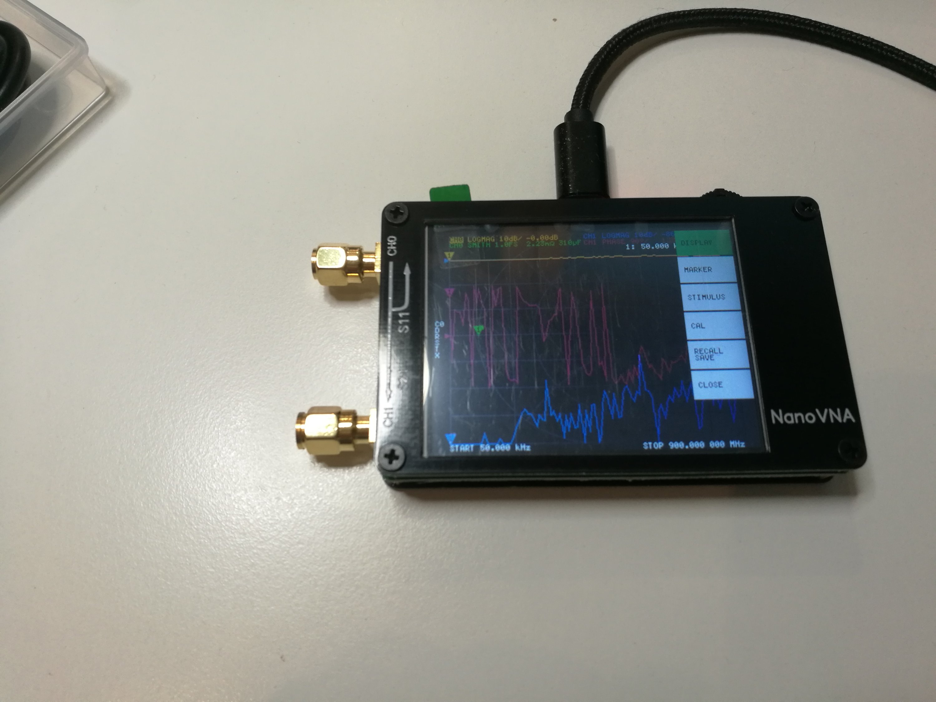
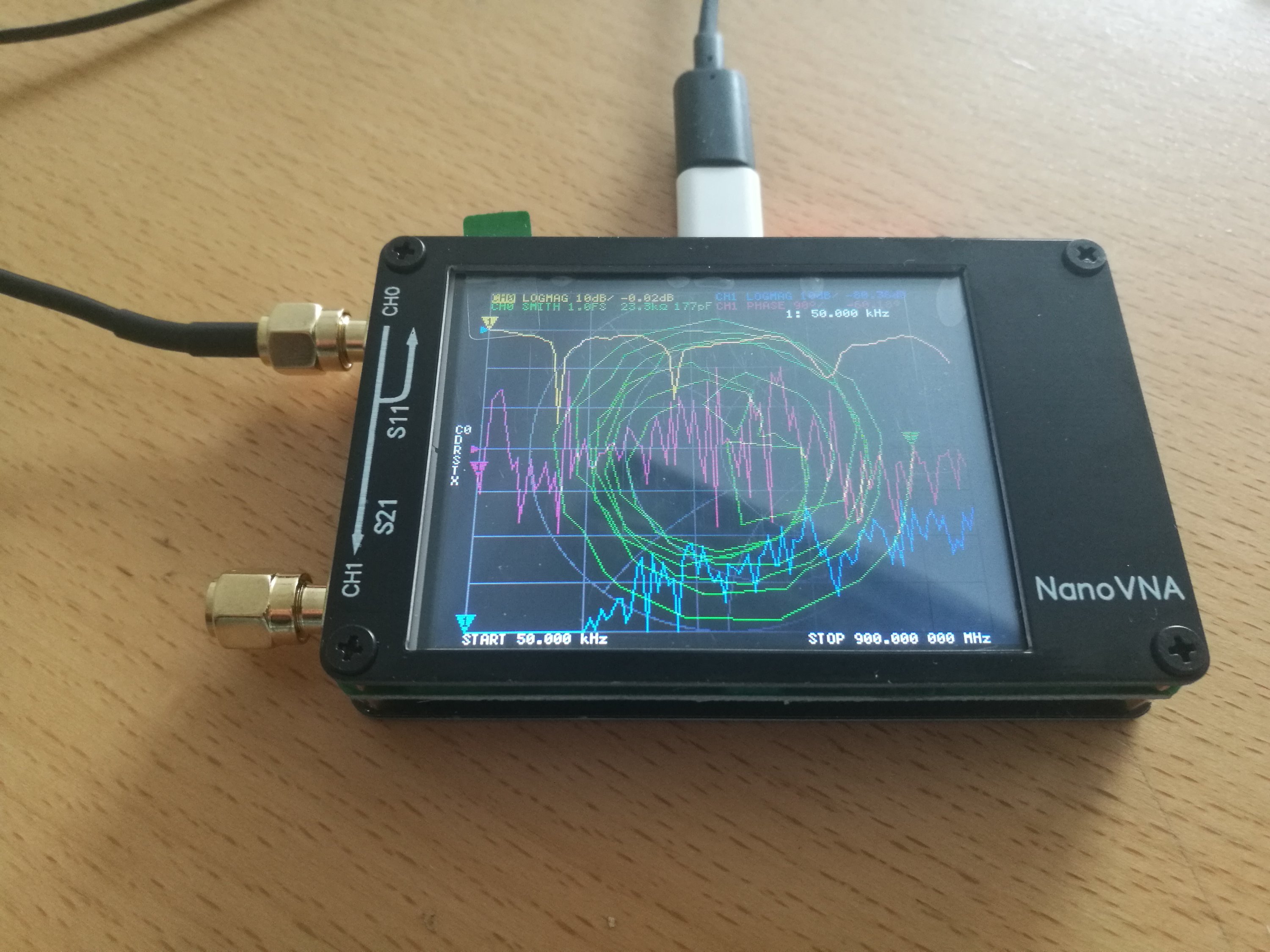
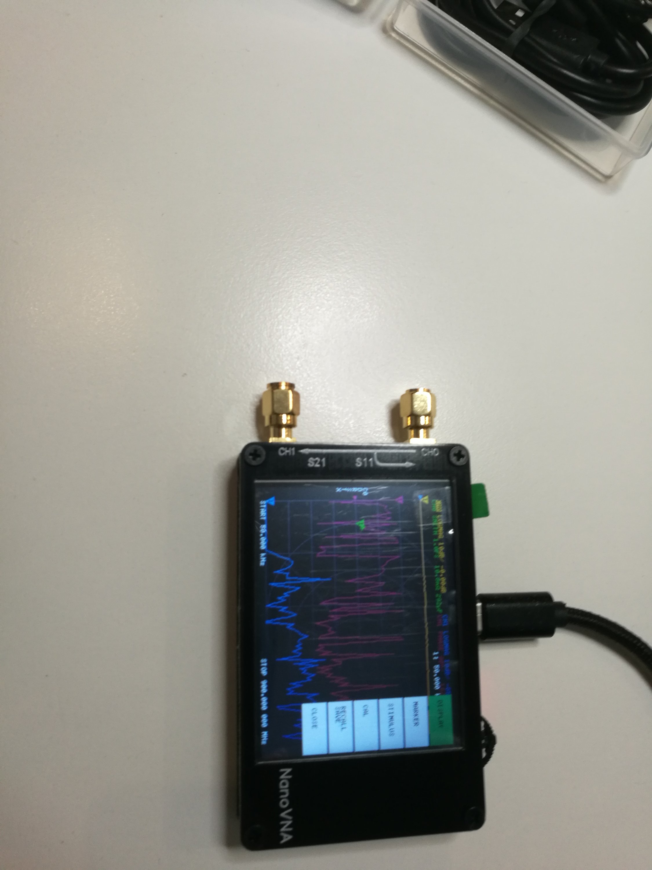
NanoVNA is very tiny handheld Vector Network Analyzer (VNA). A vector network analyzer (VNA) is an instrument that can be used to measure antenna or coax parameters such as SWR, impedance and loss. It can also be used to characterize and tune filters. It is a very useful tool to have if you are building and tuning home made antennas, filters or other RF circuits.
Earlier VNAs have been considered to be be very expensive instruments costing thousands or tens of thousands of dollars so they have only been available on advanced RF laboratories. But now the cost has come down. Nowadays there are cheaper alternatives available. Thank’s to NanoVNA the cost of owning a VNA has now been reduced to only US$50 thanks to the NanoVNA. The open source NanoVNA project by @edy555 and ttrftech has been around since 2016, but only recently have Chinese sellers begun mass producing the unit and selling them
NanoVNA is advertised as a standalone device with LCD display, portable device with battery. It can also controlled with PC software.The frequency range is from 50 kHz to 900 MHz. I had earlier posted some videos on this device to http://www.epanorama.net/newepa/2019/08/11/nanovna-handheld-vector-network-analyzer-vna/
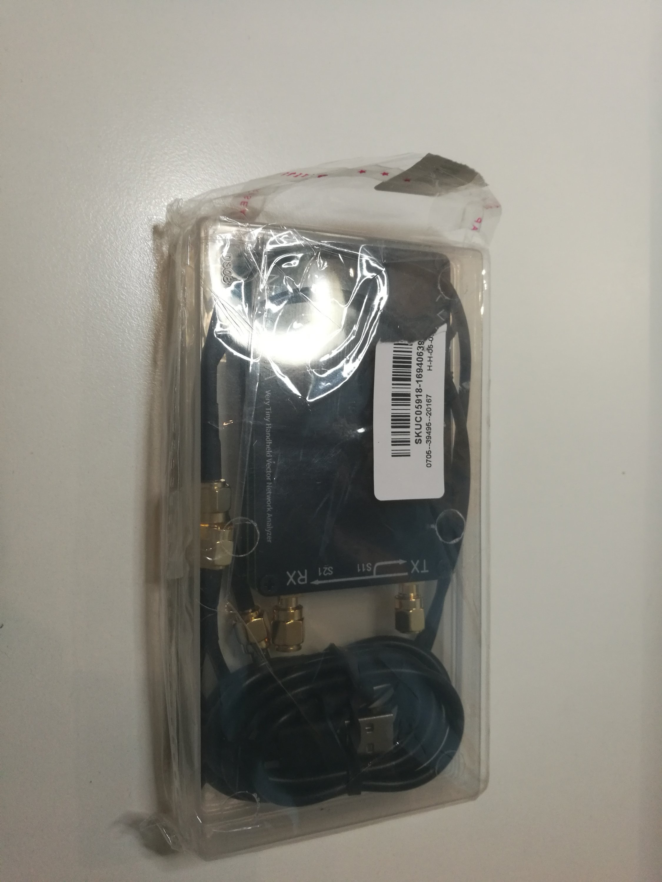
There are a ton of people selling them out of China. I ordered mine from my trusted source Banggood.com that sells one for around $65. Here is the device I received:

NanoVNA Vector Network Analyzer 50KHz – 900MHz Digital Display Touch Screen Shortwave MF HF VHF UHF Antenna Analyzer Standing Waveis a a DIY product with vector network measurement function. It includes a 2.8-inch touch screen, TX/RX measurement, can determine the complete S11 and S21 parameters (claimed that can be modified to measure S12 and S22). Here is the technical data from product page:
● RF output: -13dbm (maximum -9dbm)
● Measurement range: 70dB (50kHz-300MHz), 60dB (300M-600MHz), 50dB (600M-900MHz) enable extended firmware);
● Port SWR: < 1.1
● Display: 2.8 inch TFT (320 x240)
● USB interface: USB type-C communication mode: CDC (serial)
● Power: USB 5V 120mA, can use battery powered, maximum charging current 0.8A (battery Not included )
● Number of scanning points: 101 (fixed)
The firmware for the device is open source and available at https://github.com/ttrftech/NanoVNA. The device schematics are also available there.

The product package included NanoVNA device, USB Type-C data cable, two 30mm SMA male to male cable and test connectors, one SMA female to female connector and calibration parts (SMA connector with open, short circuit and 50 ohms terminator). Everything came in a nice plastic box that is useful for storing and transporting all the parts.


There is also PC software to work with this device. The device home page had software package that included NanoVNA v1.01 software did not work for me. After some Googling I found a discussion on the problem with this software on some countries (it was . vs , issue on number presentation) and the discussion recommended to download NanoVNA v1.03 from https://drive.google.com/drive/folders/1IZEtx2YdqchaTO8Aa9QbhQ8g_Pr5iNhr. NanoVNA v1.03 worked for me.
There were also some Python software code that I did not try this time.
Other issues:
The device supports rechargeable LiPo batteries, but the batteries are not included on the model I bought because of the safety of international transportation. I also liked to have the LiPo battery installed on my device. The device has battery charging circuitry, so installing suitable LiPo battery should make it very portable instrument (500mAh battery should give offline for 2 hours). Getting suitable LiPo battery and installing it is for another article.
Sometimes I feel that it would be nice if this device has a full case. I saw one 3D printable case for NanoVNA at Thingverse. I have downloaded the files, but I have not yet had access to suitable 3D printer to print it.
Related postings:
http://www.epanorama.net/newepa/2019/08/11/nanovna-handheld-vector-network-analyzer-vna/
https://www.rtl-sdr.com/reviews-of-the-nanovna-an-ultra-low-cost-50-vector-network-analyzer/
http://www.bbrc.info/articles/nanovna
https://groups.io/g/nanovna-users
https://brainwagon.org/2019/09/02/first-test-of-the-nano-vna-on-my-beacon-antenna/
https://github.com/ttrftech/NanoVNA
https://hexandflex.com/2019/08/31/getting-started-with-the-nanovna-part-1/
https://mtmotorstables.blogspot.com/2019/08/reviews-of-nanovna-ultra-low-cost-50.html
Getting the device:
If you are interested in getting one, use this link https://www.banggood.com/NanoVNA-Vector-Network-Analyzer-50KHz-900MHz-Digital-Display-Touch-Screen-Shortwave-MF-HF-VHF-UHF-Antenna-Analyzer-Standing-Wave-p-1471576.html?p=27131452996820140438 to get the version I got. It seems that the same web shop has also a slightly cheaper version (white color) in pre-order at https://www.banggood.com/NanoVNA-Vector-Network-Analyzer-50KHz-900MHz-Digital-LCD-Display-HF-VHF-UHF-Antenna-Analyzer-Standing-Wave-USB-POWER-p-1549963.html?p=27131452996820140438
161 Comments
Tomi Engdahl says:
From https://www.facebook.com/groups/368777730463838/permalink/951284035546535/
Here is my latest video, using the nanoVNA-F.
Verification of nominal values of inductors and capacitors is a useful function of the nanoVNA. In this video I measure the actual values, compare to the marked component values, and then verify the accuracy of the method used to obtain the readings using an LC resonant tank circuit and some S21 measurements. Does a test fixture make measurements that much more accurate as opposed to using simple alligator clip leads?
nanoVNA – Alligator Clip Leads vs. VNA Test Fixture Kit – Measuring Inductors & Capacitors
https://m.youtube.com/watch?v=Y2_aytTVvFw&feature=youtu.be
Tomi Engdahl says:
How not to damage your NanoVNA when measuring SWR
https://www.youtube.com/watch?v=totwu4IbavE
He talks about the possibility of static build up on antennas and how it can damage the input of a nanoVNA (or any measuring equipment upon connecting both for a measurement).
Saw this video some time ago and now was a good time to implement some safety precaution as am waiting for parts to continue with my antenna building, testing, and experimenting.
Used a Neon Bulb (NE-2) as a gas discharge tube, two 1N5711 Schottky diodes connected back-to-back to limit voltage swing to 0.4 Volts. Had an empty tin can and a couple of BNC connectors laying around. Took but an hour and a half of fun building. The nanoVNA measures SWR <1.2:1, and insertion loss < 0.1 dB, 1-30 MHz.
A much cleaner build, probably very good for VHF/UHF, can be found at: https://www.qrpforum.de/index.php?attachment/23764-nanovna-input-protector-pdf/
Tomi Engdahl says:
Perhaps It’s Time To Talk About All Those Fakes And Clones
https://hackaday.com/2022/12/05/perhaps-its-time-to-talk-about-all-those-fakes-and-clones/
We all like cheap instruments, whether they are a logic analyser, an SDR, a spectrum analyser, or whatever. Sometimes the cheap products are based upon open source projects, such as the NanoVNA vector network analyser we looked at a while back, but it’s important to be aware that just as often they are clones of commercial products that have had a huge research and development applied to create them.
There may be some open-source enthusiasts who would respond that all such things should be open source hardware anyway, and that the devices have been somehow “set free” by the cloners.
Tomi Engdahl says:
https://groups.io/g/nanovna-users/topic/reduce_frequency_range/68531352
Tomi Engdahl says:
Building and Using the AVNA1 Audio Vector Network Analyzer
A Teensy 3.6 based analyzer that measures impedance and transmission from 10 Hz to 40 kHz.
http://www.janbob.com/electron/AVNA1/AVNA1.htm
Tomi Engdahl says:
Extending the Frequency Range of a “Classic” NanoVNA
https://gm8bjf.joomla.com/20-extending-the-frequency-range-of-a-classic-nanovna
The Si5351A data sheet specifies its maximum output frequency as 200MHz but the designers have found that in practice most of the chips are able to operate to 300 MHz. As the outputs from the clock generator chip are square waves they are rich in odd harmonics and by generating LO and test signals whose third harmonics are spaced by 6 kHz it is possible to extend the frequency range to 900 MHz.
Extending the Frequency Range
Over the past year newer versions of the firmware have appeared on Github and the Nanovna IO group that extend the frequency range of the unit up to 1500 MHz by using the fifth harmonic of the Si5351A output. I was curious to see how well it would work and so I re-flashed the firmware in my unit with the DFU files uploaded to Github by Dislord, [1].
There are extensive guides to flashing firmware to STM32F microcontrollers on the internet and Youtube so I will not cover it here.
Conclusion
Overall the unit has become useful as an indicator of performance at frequencies in the 23cm amateur band and the additional capacitors have reduced the noise on the traces at frequencies in its original operating range improving the dynamic range there as well. There may still be some scope for further noise reduction.
Tomi Engdahl says:
Nanovna test board kit
https://www.aliexpress.com/i/4000928040725.html
https://www.aliexpress.com/item/1005004398014119.html
Tomi Engdahl says:
Traditional VNA instruments use directional couplers as shown n the diagram to separate forward and backward traveling waves in the coax and then display things like S11 = Vreflected/Vforward, etc. The NanoVNA does this with a clever resistor and amplifier arrangement and associated math. Some info is here: https://oristopo.github.io/nVhelp/html/hardware.htm